

- 1. Why calibration decides the tolerance, not the die
- 2. The five calibration methods and when each is correct
- 3. Vacuum: how much, and where
- 4. Cooling: length, temperature and the arithmetic of line speed
- 5. Sizing sleeve design
- 6. Drawdown and the haul-off
- 7. Calibration troubleshooting
- 8. Putting the line together: a worked example
- 9. Frequently asked questions
Why calibration decides the tolerance, not the die
The die produces a shape. The calibrator produces a dimension. Those are different jobs, and confusing them is the most common reason a profile project goes wrong.
A die can be perfectly balanced, delivering a dimensionally even extrudate, and the finished profile can still be 0.4 mm out of tolerance — because the calibrator failed to hold it while it cooled. Conversely, a die with a small residual imbalance can be nursed into tolerance by a calibrator that pulls the profile into shape. The second case is fragile and expensive; the first is normal production.
What calibration actually does:
- Holds the outside dimensions while the polymer is still soft enough to be shaped but cool enough not to stick.
- Removes heat, which is what sets the final dimensions. Cooling rate determines shrinkage, and uneven cooling determines whether the profile is straight or bowed.
- Sets the surface — the first 100 mm of contact with a polished sleeve is where the profile's surface finish is decided.
The window is narrow. A profile enters the calibrator at 160 – 190 °C and has to be below its glass transition or softening point by the time it leaves. That is typically 3 – 8 seconds. Everything about calibration design — tank length, vacuum level, water temperature, sleeve material — is about achieving that in the available distance at the available line speed.
The five calibration methods and when each is correct
| 方法 | How it works | 最適 | Limitation |
|---|---|---|---|
| Vacuum sizing (wet) | Profile pulled onto a perforated sleeve by vacuum, cooled by water spray or immersion | Most hollow and complex profiles | Water carry-over, needs drying |
| Vacuum sizing (dry) | Short dry sleeve with vacuum, then air cooling | Profiles that tolerate slow cooling; water-sensitive resins | Slow; needs long cooling conveyor |
| Pressure sizing (internal) | Air pressure inside a hollow profile pushes it against an external sleeve | Large hollow sections, thick walls | Needs sealed ends; complex to control |
| Roller sizing | Opposed rollers hold the profile to dimension | Simple solid profiles, sheet-like sections | Cannot hold hollows or fine detail |
| Free cooling / drawdown | No calibrator; dimension set by die and haul-off speed | Loose-tolerance profiles, rod, some monofilament | Poor dimensional control (±0.3 mm or worse) |
Vacuum sizing dominates profile extrusion because it is the only method that holds a complex hollow section in two axes at once while removing heat.
Why vacuum sizing works
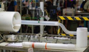
A perforated sleeve, slightly larger than the finished profile, sits at the tank entry. Vacuum applied behind the sleeve pulls the still-soft profile against the sleeve wall. Water sprays behind the sleeve remove heat through the metal. The profile is therefore held to the sleeve's dimensions while it is cooled below the point where it can deform.
The sleeve is usually brass for PVC (good heat transfer, easy to re-machine), aluminium for larger profiles, and stainless for corrosive or medical compounds. It is a consumable — a brass sleeve on an abrasive compound may need replacing in 12 – 24 months.
Vacuum: how much, and where
Vacuum level is the most over-adjusted parameter on a profile line. More vacuum is not better — it pulls the profile harder into the sleeve, which increases friction, raises haul-off load, and on thin walls produces visible dimples at the vacuum slots.
| Profile type | Typical vacuum | 備考 |
|---|---|---|
| Small solid profile (< 30 mm) | 0.02 – 0.05 MPa | Low; the profile is stiff enough to hold itself |
| Medium hollow profile | 0.04 – 0.08 MPa | Most common range |
| Large hollow / multi-wall | 0.06 – 0.09 MPa | Needs vacuum distributed over a long sleeve |
| Thin-wall tube | 0.03 – 0.06 MPa | Higher vacuum collapses the tube |
| Flexible / TPE profile | 0.02 – 0.04 MPa | Low; the profile deforms easily and sticks |
Measured at the tank, not at the pump. A gauge at the pump reads 20 – 40 % higher than the vacuum actually reaching the sleeve, because of leakage and long lines.
Where the vacuum is applied matters as much as how much:
- The first 30 – 50 mm of the sleeve does most of the shaping. Vacuum slots here need to be dense and close to the profile edge, especially at corners.
- Corners need their own slots. A corner is where the profile is least able to be pulled into shape and where air is most likely to be trapped. A sleeve with slots only on the flats produces profiles with rounded corners.
- Downstream slots are for holding, not shaping. They can be sparser and at lower vacuum.
- Never put a slot where the profile will be visible. Every slot leaves a faint witness mark. On a visible face, use a slot behind a feature or accept a matte band.
Cooling: length, temperature and the arithmetic of line speed
Cooling is a heat-transfer problem with a hard constraint: the profile has to be rigid enough to be pulled by the haul-off without deformation. That sets the cooling length, and the cooling length sets the line speed.
Cooling length rule of thumb: 1 m of water cooling per 1 mm of wall thickness for PVC at 1 m/min, scaling inversely with line speed. A 3 mm wall running at 3 m/min needs about 1 m of effective cooling; at 6 m/min it needs about 2 m. Add 30 – 50 % for multi-wall profiles where the inner walls cool more slowly.
| 素材 | Water temperature | Relative cooling length | 備考 |
|---|---|---|---|
| Rigid PVC | 15 – 25 °C | 1.0× | Reference material; cools predictably |
| CPVC | 20 – 30 °C | 1.1× | Higher Tg, needs warmer water to avoid stress |
| 高密度ポリエチレン | 15 – 25 °C | 1.3× | High shrinkage, high crystallinity |
| PP | 20 – 35 °C | 1.4× | Slow crystallisation; warm water improves surface |
| ABS | 20 – 40 °C | 1.1× | — |
| PC | 40 – 70 °C | 1.5× | Warm water essential — cold water causes stress cracking |
| PMMA | 30 – 50 °C | 1.3× | Cold water produces internal stress and crazing |
| PA | 40 – 80 °C | 1.4× | Needs hot water for dimensional stability |
| POM | 30 – 60 °C | 1.2× | — |
| TPE / TPV | 10 – 25 °C | 0.9× | Cools fast but is easily deformed while warm |
"Relative cooling length" is the multiplier on the PVC figure. Polycarbonate needing 1.5× is not a small difference — it is the reason PC profiles are usually run at half the line speed of the same PVC profile.
Three cooling mistakes that show up as dimensional problems:
- Too cold, too early. Quenching a PC or PMMA profile in 15 °C water freezes in stress that shows up as crazing weeks later, or as a profile that cracks when drilled. The water temperature should be close to the material's Tg minus 60 – 80 °C, not as cold as the chiller can go.
- Uneven cooling around the section. If one side of the profile is sprayed and the other is only splashed, the two sides shrink differently and the profile bows. On a long tank, check that every face gets the same spray pattern.
- Cooling the outside only. A thick wall cools from the outside in, so the core is still hot when the profile leaves the tank. It then shrinks further on the cooling conveyor, and the final dimension is smaller than the one measured at the tank exit. Measure after the conveyor, not before.
Sizing sleeve design
The sleeve is the most precisely made part of the whole line, and the one that wears out. Its internal dimensions are the finished profile dimensions plus the shrinkage that will happen after the profile leaves it.
| Sleeve feature | Design rule | なぜ |
|---|---|---|
| Entry taper | 2 – 5° included, 5 – 15 mm long | Guides the profile in without shaving it |
| Internal dimension | Finished size + 0.5 – 1.5 % (material dependent) | Compensates for post-calibration shrinkage |
| Vacuum slot width | 0.5 – 1.0 mm | Wide enough to pull air, narrow enough not to dimple |
| Slot depth behind | 2 – 4 mm manifold | Distributes vacuum along the sleeve |
| Length | 1.5 – 3 × the profile's largest dimension | Long enough to hold, short enough to keep friction manageable |
| Surface finish | Ra 0.2 – 0.4 µm, polished along the flow direction | Reduces friction and sets the profile's surface |
| 素材 | Brass (PVC), aluminium (large), stainless (corrosive) | Heat transfer, machinability, corrosion |
The entry taper is the detail most often got wrong on a first sleeve. A sharp entry shaves the profile, producing a continuous stream of plastic swarf and a scratched surface.
Drawdown and the haul-off
The haul-off pulls the profile faster than it exits the die, which stretches it. The ratio of die orifice to finished size is the drawdown, and it interacts with everything else.
| Drawdown | Effect on dimensions | Effect on properties | When to use |
|---|---|---|---|
| 1.00 – 1.05 | Easiest to control | Low orientation | Close-tolerance profiles, thick walls |
| 1.05 – 1.15 | Normal production | Moderate orientation | Most profiles |
| 1.15 – 1.30 | Harder — dimension drifts with haul-off speed | Higher longitudinal strength, higher shrinkage | Thin walls where die swell is a problem |
| > 1.30 | Very difficult — small speed changes move dimensions | Strong anisotropy, warpage risk | Rare; only for specific thin sections |
Drawdown is the reason haul-off speed is a dimensional control, not just a rate control. On a line running 1.2 drawdown, a 1 % change in haul-off speed changes the profile width by about 0.5 %.
The haul-off itself matters: belt haul-offs are standard for profiles, with 2 – 6 belts depending on section. The belts must be synchronised and at the same pressure, or the profile is pulled slightly sideways and comes out with a consistent bow.
Calibration troubleshooting
| Symptom | Likely calibration cause | First check |
|---|---|---|
| Profile too small overall | Excess drawdown, or sleeve worn oversize | Haul-off speed ratio; measure sleeve |
| Profile too large overall | Insufficient drawdown, or insufficient cooling (shrinks later) | Measure after conveyor, not at tank |
| Corners rounded | No vacuum at corners, or vacuum too low | Slot position at corners; vacuum at sleeve |
| Dimples on a face | Vacuum too high, or slots too wide | Reduce vacuum 20 %; check slot width |
| Surface scratches, longitudinal lines | Dirt in sleeve, or entry taper damaged | Inspect and polish sleeve |
| Profile bows to one side | Uneven cooling, or uneven belt pressure | Spray pattern; belt pressures |
| Profile twists | Uneven cooling around the section, or asymmetric wall | Rotate the spray; check wall balance |
| Dimensions drift over hours | Sleeve wear, or water temperature drift | Log water temperature; measure sleeve |
| Profile sticks in the sleeve | Too hot at entry, or insufficient release | Lower melt temperature; check water flow |
| Internal walls collapsed | Vacuum too high for the wall thickness, or no internal support | Reduce vacuum; add internal air pressure |
The first thing to check on any dimensional complaint is whether the profile is measured at the tank exit or after the cooling conveyor. Half of all "out of tolerance" reports are measured too early.
Putting the line together: a worked example
A rigid PVC window bead, 60 mm wide, 12 mm deep, wall 2.5 mm, target 0.3 mm tolerance on width, target output 180 kg/h.
| Decision | Value chosen | Reasoning |
|---|---|---|
| Die orifice width | 57.5 mm (4 % undersize) | Allows 1.05 drawdown and 1.08 swell compensation |
| Land length | 25 mm | 10 × wall thickness for surface quality |
| Sleeve internal width | 60.4 mm | Finished 60.0 mm + 0.7 % post-shrink |
| Sleeve length | 120 mm | 2 × the largest dimension |
| Vacuum | 0.05 MPa | Medium hollow range, enough for corners |
| Water temperature | 18 °C | Standard for rigid PVC |
| Tank length | 3.5 m | 2.5 mm wall needs ~2.5 m; 40 % margin for speed |
| Line speed | 2.6 m/min | Set by output and cross-section area |
| Drawdown | 1.04 | Low — tolerance is the priority, not thin-wall forming |
Each of these numbers interacts. Raising line speed to 4 m/min would need a longer tank or colder water, and colder water on rigid PVC increases residual stress and the risk of impact failure in service.
Frequently asked questions
What is vacuum calibration in profile extrusion?
Pulling the still-soft profile against a perforated metal sleeve with vacuum, while water removes heat through the sleeve. It holds the outside dimensions to the sleeve's size until the polymer is cool enough to keep them. It is the standard method for hollow and complex profiles.
How much vacuum should I use?
Typically 0.04 – 0.08 MPa at the tank for most profiles, measured at the sleeve rather than at the pump. Use the lowest vacuum that holds the shape — higher vacuum increases friction, raises haul-off load and produces dimples at the slots.
How long does a calibration tank need to be?
Roughly 1 m of effective water cooling per 1 mm of wall thickness for PVC at 1 m/min, scaling inversely with speed. A 3 mm wall at 3 m/min needs about 1 m; at 6 m/min about 2 m. Add 30 – 50 % for multi-wall profiles.
Why is my profile the right size at the tank but undersized after cooling?
The core was still hot when it left the tank, so it continued to shrink on the conveyor. Either extend the cooling or measure the sleeve against the post-conveyor dimension rather than the tank-exit dimension. This is one of the most common tolerance disputes in profile extrusion.
Why are the corners of my profile rounded?
Usually no vacuum at the corners. Vacuum slots are often placed on the flats because that is where there is room, but a corner cannot be pulled into shape without its own slot. Add slots within 5 mm of each corner.
Why does my profile bow?
Uneven cooling around the section. The side that cools first shrinks first and pulls the profile toward it. Check the spray pattern, the water distribution along the tank, and the belt pressures on the haul-off.
Can I calibrate a profile without vacuum?
Yes, with roller sizing or free cooling, but dimensional control is much worse — typically ±0.3 mm or more. It is only appropriate for loose-tolerance profiles where the section is stiff enough to hold itself.
What water temperature should I use?
15 – 25 °C for rigid PVC and polyolefins, but 40 – 70 °C for PC, PMMA and PA. Cold water on those materials freezes in stress that shows up later as crazing or cracking. The rule is to cool fast enough to set the dimension but not so fast that you quench stress into the wall.
How often does a sizing sleeve need replacing?
12 – 36 months on unfilled PVC, much sooner on abrasive or glass-filled compounds. Wear shows as a profile that grows slowly oversize and cannot be brought back by adjusting the line. Measuring the sleeve at every major service is the only way to catch it early.
Does calibration affect the mechanical properties of the profile?
Yes, significantly. Fast cooling produces a thinner skin, more residual stress and lower impact strength; slow cooling produces better crystallization and better impact but slower lines. On PVC window profiles, cooling rate is one of the main levers on impact performance.
Trouble holding tolerance on a profile? Send us the section and the symptom
We will tell you whether it is the die, the sleeve or the cooling — and what to change first. A drawing plus one photograph of the problem usually settles it.




 JA
 EN
 ES
 FR
 DE
 PT
 AR
 RU
 KO
 IT
 NL
 TR
 PL
 ID
