
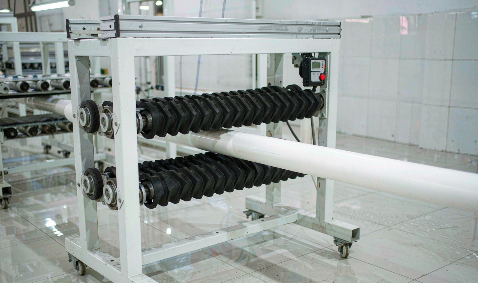
The haul-off is the wall control
An extruder delivers a fixed volume of melt per revolution. The die gives that melt a shape. The haul-off decides how fast the shaped melt is pulled away, and therefore how much of it ends up in each metre of product. That is the whole mechanism, and it is why the wall thickness on a running line is set by the haul-off and not by the screw.
This surprises people who come from injection moulding, where the wall is in the tool. In extrusion the die only sets the ratio between wall and width. The absolute thickness is a product of mass balance: output in kilograms per hour divided by line speed in metres per hour, divided by the density and the cross-section.
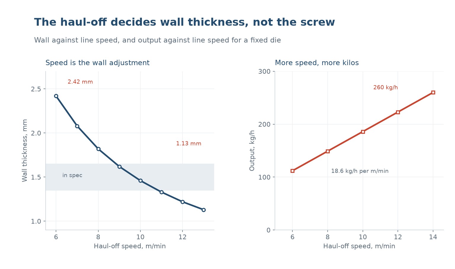
So a die that was cut for a 2.4 mm wall at 6 metres per minute will produce a 1.2 mm wall at 12 metres per minute, provided the extruder can still deliver the melt at the same pressure. The product gets thinner and narrower at the same time, and both changes come from the same dial.
The practical consequence is that the haul-off is the first thing to check when a wall is out of tolerance, and the last thing anyone adjusts. Operators tend to change temperature or screw speed because those feel like the controls that matter. Both of them change the wall far less than the haul-off does.
Speed against wall is close to inverse
On a 40 mm PVC pipe line with a fixed die and a fixed screw speed, the wall measured 2.42 mm at 6 metres per minute, 2.08 at 7, 1.82 at 8, 1.62 at 9, 1.46 at 10, 1.33 at 11, 1.22 at 12 and 1.13 at 13.
The relationship is close to inverse but not exactly, because the die swell changes with speed. At low speed the melt has more time to relax as it leaves the die, so it swells more and the wall is thicker than the mass balance alone would predict. At high speed the swell is suppressed by the pull, and the wall falls faster than 1 over speed.
That is why a wall that is 5 percent heavy cannot be fixed by a 5 percent speed change and left alone. The correct procedure is to change speed, wait for the line to settle for two or three minutes, measure again, and iterate. On a line with a good gravimetric feeder the settle is faster because the output is held constant while the speed changes.
The other thing to watch is that the wall does not change evenly around the profile. Increasing speed pulls the thin sections thinner faster than the thick ones, because the thin sections are cooler and have less melt to draw. A profile that was within tolerance at 8 metres per minute can be out of tolerance on one wall only at 12.
Drawdown: what happens to the width
Pulling faster does not only thin the wall. It also pulls the profile narrower, because the material has to come from somewhere. The ratio between the die opening and the finished size is the drawdown ratio, and it is the number that should be written on the die drawing.
For pipe, a drawdown ratio of 1.02 to 1.08 is normal, and the sizing sleeve holds the outside diameter while the wall thins. For profile, the ratio can be much larger, and a ratio above about 1.3 starts to distort the section: corners round off, thin legs bend inward, and the shape stops matching the die.
The reason is that drawdown is not uniform. The outside of the profile is cooler and more viscous than the core, so it resists being pulled. Corners have more material and cool slower, so they draw more than the flats. The result is a section that is not a scaled version of the die but a distorted one.
This is why profile dies are cut oversize by a specific amount for a specific speed, and why running a profile line at half its design speed produces a part that is too thick, too wide and often out of shape in a way no temperature adjustment will fix.
| Drawdown ratio | Typical use | What goes wrong |
|---|---|---|
| 1.02 - 1.08 | Pipe and tube | Nothing, this is the design point |
| 1.08 - 1.20 | Simple profiles | Corners round slightly |
| 1.20 - 1.30 | Thin-wall profiles | Legs pull in, tolerances tighten |
| > 1.30 | Rarely intentional | Section distorts, sizing struggles |
Table 1 — Drawdown ratio against section behaviour
Output rises with speed, up to a limit
Because the die is fixed, running faster consumes more material per hour. On the same line, output went from 112 kilograms per hour at 6 metres per minute to 260 at 14, a slope of about 18.6 kilograms per hour for each additional metre per minute.
That slope is the linear density of the product at that wall thickness, and it is why the wall falls as speed rises: the extruder can only deliver so much. Once the extruder is at its maximum output, further speed increase does not raise the output, it just thins the wall.
This is the single most useful diagnostic on an extrusion line. If turning the haul-off up does not change the output reading on the feeder, the line is extruder-limited and the wall will keep falling until the product is out of spec. If the output rises proportionally, the line is haul-off-limited and there is capacity in hand.
Most lines are extruder-limited most of the time, because the extruder was sized for a product that was later made thinner to save material. The result is a line that runs fast, makes a thin product and has no margin to correct anything.
Slippage: the error nobody measures
The speed on the display is the speed of the belt, not the speed of the product. If the belt slips, the product runs slower than the display says, and the wall comes out thicker than the calculation predicts. This is the most common reason a line that has been running for years suddenly cannot hold tolerance.
Slippage comes from three places: worn belt pads, too little clamping pressure, and water or talc on the product. A caterpillar haul-off with worn pads grips on a smaller area, so the pressure per unit area rises and the product deforms locally instead of being held. The symptom is ovality at the haul-off that disappears downstream.
The check is simple. Mark a metre on the product, time it with a stopwatch, and compare with the display. A 2 percent error is normal and harmless; 5 percent means the belt needs attention, and any error at all means the wall calculation has to be based on the measured speed, not the dial.
On a line with a laser diameter gauge and a gravimetric feeder, the control system can close the loop itself: it measures the wall or the diameter and trims the haul-off. That is worth having on any line that runs more than one product, because it removes the operator from the iteration.
| Symptom | Likely cause | Check |
|---|---|---|
| Wall heavy at the set speed | Belt slipping | Mark and time a metre against the display |
| Ovality at the haul-off only | Worn pads, local crushing | Inspect pad wear and clamping pressure |
| Wall drifts over a shift | Feeder or screw wear | Compare output reading against weighed scrap |
| One wall out, others fine | Die or sizing, not speed | Measure around the section, not just one point |
| Output flat as speed rises | Extruder at maximum | Read the feeder load and the head pressure |
Table 2 — Haul-off faults and how to separate them
Setting speed from a measured wall
The reliable procedure takes about twenty minutes and does not depend on the dial being right. Run the line at the current speed, let it settle, cut a sample, measure the wall at four points around the section, and average. Then calculate the speed that would give the target wall, assuming an inverse relationship, and change to it.
Then measure again. The second measurement tells you the actual exponent for that die and that material, which is usually between 0.9 and 1.1 rather than exactly 1.0. Write it on the setup sheet. From then on the line can be set from the sheet in one step instead of three.
Do this at the speed the line will actually run, not at a slow proving speed. A line proved at 5 metres per minute and then run at 12 will not hold the wall it was proved at, because the drawdown behaviour is different. Proving at production speed is the only way to get a setup sheet that means anything.
And record the output at that speed, because it is the second half of the story. A setup sheet with a speed and a wall but no output cannot tell the next operator whether the line is running correctly or whether the extruder is struggling.
When the haul-off is the bottleneck
A haul-off limits the line when the belts cannot grip hard enough to pull the product at the speed the extruder could support. The symptoms are slip marks, a wall that will not go thin, and a motor running at its current limit while the line speed sits below target.
The fix is usually mechanical rather than electrical: more belt length in contact, better pads, or a second haul-off in series. A second unit downstream, running slightly faster, takes some of the pull and lets the first one hold the profile without crushing it. On large profiles this is standard, and it also improves dimensional stability.
The other limit is the cutter. A saw or a guillotine cannot follow a line above a certain speed, so the haul-off is capped by whatever is downstream. That is a separate constraint and it is worth knowing which one is binding before anyone buys a bigger motor.
Does higher haul-off speed make the wall thinner?
Yes, on a fixed die. The extruder delivers a fixed mass per hour, so running faster spreads that mass over more metres and the wall falls roughly in inverse proportion.
How do I know if my line is extruder-limited or haul-off-limited?
Watch the output reading as you raise the speed. If output rises with speed, the haul-off is the limit. If output is flat, the extruder is at maximum and the wall will keep thinning.
What drawdown ratio is normal?
1.02 to 1.08 for pipe and tube, up to about 1.2 for simple profiles. Above 1.3 the section starts to distort and sizing becomes difficult.
Why is my wall heavier than the calculation says?
Usually belt slip. The display shows belt speed, not product speed. Mark a metre, time it, and compare; a 5 percent error is enough to explain a heavy wall.
Can I run a profile line slower than its design speed?
You can, but the wall will be heavy and the section will be wider than the die was cut for. Profile dies are cut oversize for a specific drawdown, so speed is part of the tool design.
Should I set the wall with speed or with the die?
With speed, within the range the die was cut for. If the target wall needs a drawdown the die was not designed for, the die is wrong and no amount of speed adjustment will give a good section.
A line that will not hold its wall?
Send the die drawing, the material and the speed the line runs at. We will tell you whether the wall problem is speed, drawdown or the die itself.




 JA
 EN
 ES
 FR
 DE
 PT
 AR
 RU
 KO
 IT
 NL
 TR
 PL
 ID
