
- 1. The hardest large part in the plant
- 2. Draw depth is a thickness budget
- 3. The temperature window is narrow and it moves
- 4. Where webbing actually starts
- 5. Tooling: aluminium, temperature and vacuum holes
- 6. Cooling, and the fixture that keeps it straight
- 7. What the dimensional report should say
The hardest large part in the plant
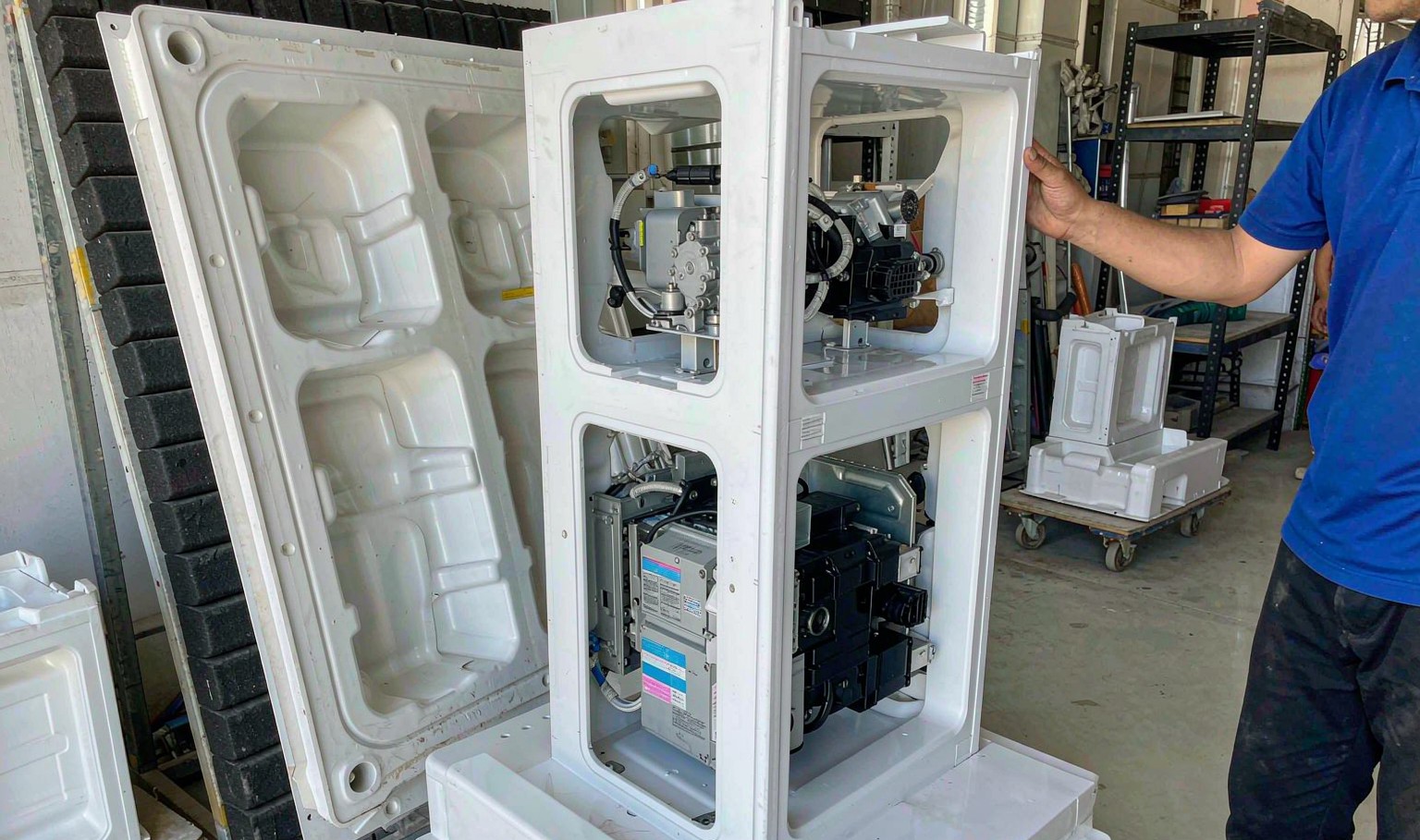
A refrigerator liner is a single sheet of high impact polystyrene or ABS drawn into a box roughly 550 mm wide, 1,300 mm tall and 400 mm deep, with shelf grooves, a compressor recess, lamp pockets and a drain channel formed in one shot. It is not a complicated shape. It is a very deep one, and depth is what a thermoformer cannot fake.
The part has to be within a millimetre or two over its whole length, because it slides into a steel cabinet and the foam is injected behind it. A liner that is 3 mm long at the top will not seat, and a liner that is 3 mm short leaves a gap that the foam fills and the customer sees.
It also has to be food safe, it has to survive the foaming pressure without collapsing, and it has to look right, because the inside of a fridge is a surface the buyer looks at every day for fifteen years.
So the liner sits at the intersection of the three things that make thermoforming hard: a deep draw, a tight tolerance and a cosmetic surface. Every one of them pulls the process in a different direction.
Draw depth is a thickness budget
Vacuum forming does not add material. It takes a flat sheet of uniform thickness and stretches it over a tool, and the material that ends up at the bottom of a deep pocket came from somewhere. The somewhere is the wall of that pocket, which thins as it draws.
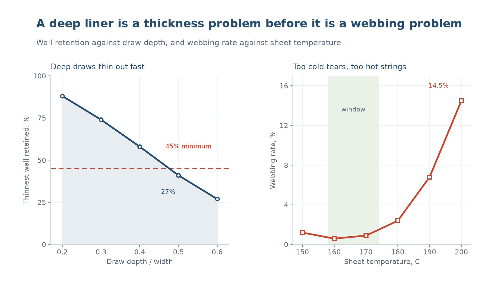
The number that predicts how much is the draw ratio, the depth of the draw divided by its width. At a ratio of 0.2, a shallow pan, the thinnest wall keeps about 88 percent of the sheet thickness. At 0.3 it is 74 percent, at 0.4 it is 58, at 0.5 it is 41, and at 0.6 it is 27.
A fridge liner sits at 0.45 to 0.55 on that curve. Start with a 3.0 mm sheet and the bottom of the compressor recess comes out at 1.2 to 1.3 mm. That is not a defect; it is the arithmetic. What matters is whether 1.2 mm is enough for the foam pressure and the shelf load, and whether the sheet grade was chosen for the thickness the part will actually have rather than the thickness it started with.
This is where most liner problems begin. A moulder changes from a 3.2 mm sheet to a 2.8 mm sheet to save material, and the bottom of the recess goes from 1.3 mm to 1.15 mm. Nothing in the process looks different. The part that fails is the one that cracks at the recess corner after foaming.
The temperature window is narrow and it moves
The sheet has to be hot enough to stretch and cool enough to hold. Below the window the material is stiff, it resists the draw, and the pocket bottom tears or the corners pull thin enough to fail. Above it the sheet is soft enough that the material flows sideways instead of stretching, and it folds into a web between two adjacent pockets.
Measured on a 3 mm high impact polystyrene sheet, the webbing rate is 1.2 percent at 150 C, dips to 0.6 at 160, and is still under 1 percent at 170. By 180 it is 2.4 percent, at 190 it is 6.8, and at 200 it is 14.5. The usable band is roughly 158 to 174 C, about 16 C wide.
Sixteen degrees sounds generous until you measure the sheet. A radiant heater bank does not deliver a uniform temperature across a 1.5 m sheet, and the difference between the centre and the edge of a badly zoned oven is easily 20 C. On that oven there is no single setpoint that works for the whole sheet, and the operator compensates by running hot, which is where the webbing comes from.
The window also moves with the grade. A high impact polystyrene with a higher rubber content softens lower and webs sooner; an ABS needs 10 to 15 C more before it will draw. Changing the sheet supplier without re-running the temperature ladder is a reliable way to spend a week chasing webbing that was not there last month.
The practical fix is a zoned oven and a sheet temperature measurement, not a setpoint. An infrared pyrometer on the sheet as it leaves the oven, read at three points across the width, tells the operator what the sheet is, and the setpoint is adjusted to bring the coldest zone up rather than the average up.
Where webbing actually starts
Webbing is a sheet that has folded rather than stretched. It appears between two features that draw at the same time, most often between the two long sides of the liner and between the shelf grooves. The fold starts as a slack bridge of hot sheet that sags between two anchors, and once it has sagged it will not recover; the vacuum pulls it flat against the tool and the fold is frozen in.
Three things create that slack. The sheet is too hot, so it sags under its own weight before the vacuum arrives. The draw is too fast, so the material at the anchors takes the strain and the material between them has not had time to move. Or the tool has a feature that holds the sheet back, usually a sharp internal corner or a deep narrow groove, and the material behind it piles up.
The fixes follow the cause. Lower the sheet temperature and the sag goes away. Slow the draw with a two-stage vacuum, a low vacuum to pull the sheet into shape and a high vacuum to detail it, and the material has time to move. Round the internal corners of the tool to at least the sheet thickness and the pile-up stops.
A plug assist helps on a deep liner and it is often left out because it is extra tooling. A plug that pushes the sheet down into the cavity before the vacuum comes on distributes the stretch, and it is the difference between a 0.45 draw ratio that works and one that webs at the corners.
Tooling: aluminium, temperature and vacuum holes
A liner tool is almost always cast or machined aluminium, because the part is large, the volume is high and the tool has to be held at temperature. Aluminium conducts heat four times faster than steel, which is what lets the tool pull heat out of the sheet quickly and set the part before it can move.
Tool temperature is a process variable on a liner, not a convenience. A tool at 70 to 80 C gives a part that releases cleanly and holds its shape; a tool at 40 C quenches the surface and locks in the orientation, and the part moves when it is reheated by the foam. A tool above 90 C gives a part that is still soft on demould and stretches under its own weight.
Vacuum holes are the other half. A liner needs them everywhere the sheet has to follow a detail, and they have to be small enough not to mark the surface. A 0.8 mm hole on a 3 mm sheet leaves a dimple that is visible under the shelf; a 0.5 mm hole in the same place draws the same vacuum and leaves a mark the eye cannot find.
The holes also have to be where the air is. A deep pocket traps air in its bottom corner and a hole in the middle of the pocket floor does not clear it. The corner needs its own hole, or a groove cut from the corner to the nearest hole so the air has a path.
| Tool variable | Typical value | What it controls |
|---|---|---|
| 素材 | Cast or machined aluminium | Heat removal rate |
| Tool temperature | 70 to 80 C | Release, dimensional stability |
| Vacuum hole size | 0.5 to 0.8 mm | Detail, surface marking |
| Hole position | Corners, deep pockets, ribs | Air removal |
| Corner radius | At least sheet thickness | Webbing and thinning |
| Plug assist | Felt or syntactic foam | Stretch distribution |
Table 1 — The tool variables that decide whether a liner draws
Cooling, and the fixture that keeps it straight
A liner comes off the tool at 60 to 70 C and it is not finished. It is still shrinking, and it will keep shrinking for hours. A part that is measured on the machine and packed is a part that will be outside tolerance when the customer opens the box.
The standard answer is a cooling fixture: a frame that holds the liner in its formed shape while it cools to room temperature, usually 8 to 15 minutes on a large part. The fixture does not cool the part faster, it stops the part from distorting while it cools, which is the part that matters.
The alternative is to let it cool free and then trim it oversize, which only works if the distortion is uniform. A liner does not distort uniformly. The walls pull in, the bottom stays flat, and the result is a part that is short in one direction and long in another.
Shrinkage itself is predictable if the sheet is known. High impact polystyrene shrinks 0.4 to 0.7 percent, ABS 0.4 to 0.8, and the tool is cut oversize to match. What is not predictable is the difference between the machine direction and the cross direction of the sheet, which can be 0.3 percent, and that is why the tool is cut with a different allowance on each axis.
What the dimensional report should say
A liner drawing usually carries an overall length, an overall width, a depth, and a profile tolerance on the flange. Those four numbers do not catch the failures that matter. The failures are the ones that stop the part going into the cabinet: a twisted flange, a wall that has bowed in, a recess that is not where the compressor needs it.
A useful report measures the flange flatness on a surface plate, the wall straightness at three heights, the position of the compressor recess relative to the flange datum, and the wall thickness at eight points including the four corners of the recess. The thickness map is the one that predicts field failures, and it is the one most often left out.
It should also record the sheet temperature at the moment of forming and the tool temperature, because those two numbers explain almost every out-of-tolerance part. A report without them can tell you a part is wrong but not why.
| Failure | What it looks like | Usual cause |
|---|---|---|
| Torn pocket bottom | Split at the deepest point | Sheet too cold, draw too fast |
| Web between pockets | Folded sheet, not stretched | Sheet too hot, no plug assist |
| Twisted flange | Will not seat in the cabinet | No cooling fixture |
| Bowed wall | Gap at mid height | Tool too cold, part released early |
| Dimple marks | Visible dots under the shelf | Vacuum holes too large |
| Thin recess corner | Cracks after foaming | Sheet gauge too light for the draw |
Table 2 — The six liner failures and where they come from
Why does the bottom of a liner come out so much thinner than the sheet?
Because the material is stretched, not added. At a draw ratio of 0.5 the thinnest wall keeps about 41 percent of the sheet thickness, so a 3.0 mm sheet gives 1.2 mm at the deepest point.
What temperature should a liner sheet be formed at?
For high impact polystyrene, roughly 158 to 174 C. Below that it tears at the pocket corners; above it the sheet sags and webs between the pockets.
Can webbing be fixed with more vacuum?
No. The fold forms while the sheet is sagging, before the vacuum is full. Fix the sheet temperature, the draw speed and the corner radii first.
Does a plug assist really help on a deep liner?
Yes, on any draw ratio above about 0.4. The plug pushes the sheet into the cavity before the vacuum comes on, which spreads the stretch and keeps the corners from thinning.
Why is a cooling fixture needed if the part looks straight?
Because the part is still shrinking. A liner released free at 70 C distorts as it cools, and the distortion is not uniform between the walls and the base.
What wall thickness is safe for a foamed-in liner?
It depends on the foam pressure, but 1.2 mm at the recess corner is the usual floor. Below that the corner cracks when the foam expands.
A liner that webs, or one that will not seat?
Send the drawing, the sheet grade and the draw depth. We will tell you the draw ratio, the thickness you will actually get at the bottom, and whether the tool needs a plug assist.




 JA
 EN
 ES
 FR
 DE
 PT
 AR
 RU
 KO
 IT
 NL
 TR
 PL
 ID
