
A boss is a rib wrapped around a hole
Mechanically a boss does two jobs: it holds a thread, and it stiffens the corner it sits in. Both of those want material away from the neutral axis, and both are limited by the same constraint, which is that a thick section cools last and shrinks.
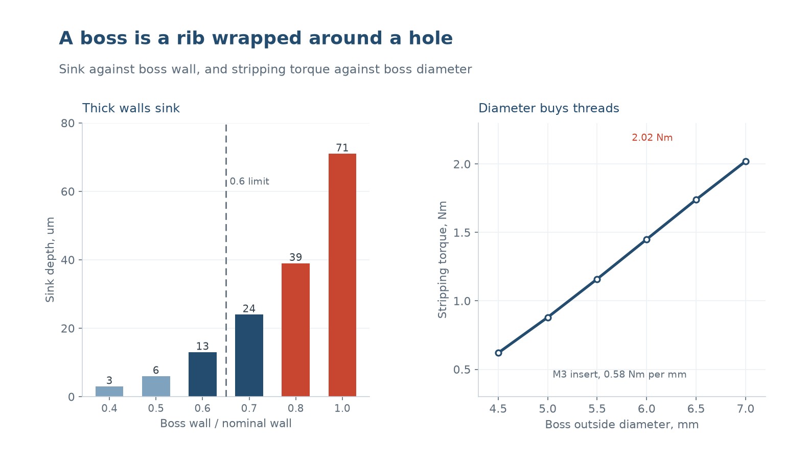
The boss wall is the number that matters. Measured against the nominal wall of the part, a boss wall of 0.4 times the wall gave 3 micrometres of sink on the opposite face, 0.5 gave 6, 0.6 gave 13, 0.7 gave 24, 0.8 gave 39 and 1.0 gave 71.
So the same 0.5 to 0.6 rule that governs ribs governs bosses, and for the same reason. A boss whose wall equals the part wall is a solid lump of plastic and will sink a visible circle on the other side, no matter what the packing profile does.
The difference from a rib is that the boss also has to survive a screw. A thin boss wall saves the cosmetic face and loses the thread: the hoop stress from a driven screw splits the boss down the side, usually at the weld line where the two halves of the melt met.
Sizing the wall against the screw
For a thread-forming screw in unfilled ABS or PC/ABS, the boss outside diameter is usually about 2.0 to 2.4 times the screw's major diameter, and the boss wall works out at roughly 0.5 to 0.6 times the nominal wall when the screw is sized to the boss rather than the other way round.
That is the design sequence that works: start from the nominal wall, apply the 0.55 ratio to get the boss wall, then see which screw fits. On a 2 mm wall that gives a 1.1 mm boss wall, and with a 5.5 mm outside diameter that is a 3.3 mm bore, which suits an M4 screw.
Working the other way, from a specified screw, usually produces a boss that is too thick for the wall. A designer who needs an M6 screw in a 2 mm wall has a problem that a boss cannot solve: the boss would need a 3 mm wall and would sink badly. The answer is a metal insert, or a thicker local section with a cored relief on the far side.
The thread engagement should be 1.0 to 1.5 times the screw diameter for a thread-forming screw, and 1.5 to 2.0 for a machine screw in a moulded or inserted thread. Less than that and the thread strips at the specified torque; much more and the screw bottoms before it seats.
| ネジ | Boss OD | Bore | Wall on a 2 mm part |
|---|---|---|---|
| M2.5 | 4.5 - 5.0 mm | 2.1 mm | 0.55 ratio, 1.1 mm |
| M3 | 5.5 - 6.0 mm | 2.5 mm | 0.55 ratio, 1.1 mm |
| M4 | 7.5 - 8.0 mm | 3.4 mm | Too thick for a 2 mm wall |
| M5 | 9.5 - 10 mm | 4.2 mm | Insert territory |
Table 1 — Screw size against boss geometry
The root fillet is where parts crack
Most broken bosses break at the root, not at the thread. The root is the corner where the boss meets the wall, and a sharp corner there is a stress concentration with a factor of two or three. A screw tightened to torque, plus a drop, plus a cold day, is enough to start a crack that runs up the boss.
A root fillet of 0.25 to 0.5 times the wall removes most of that concentration and costs nothing in tooling. Anything less than 0.25 is a sharp corner in practice, because a 0.2 mm radius is not machinable at the bottom of a pocket with any reliability.
The second crack site is the weld line. When the melt splits to flow around the boss core and meets again on the far side, the joint is weaker than the surrounding material, especially in a glass-filled resin or a semi-crystalline one. Placing the gate so the weld line lands on the stiff side of the boss, rather than on the side that takes the screw load, is worth doing at the design stage.
The third is the boss top. A boss that ends flush with a mating surface and is over-tightened will crush or split at the rim. A small chamfer or a counterbore at the top spreads the load and gives the screw head somewhere to sit.
Draft, depth and the core pin
A boss is formed by a core pin, and the core pin has to come out. Draft on the outside of the boss should be at least 0.5 degrees, and 1 degree on any boss deeper than 15 mm. On the inside, the bore needs the same draft, which means the bore tapers and the thread engagement varies with depth.
That taper is why a deep boss with a thread-forming screw is a compromise: the screw engages progressively, and the torque rises along the length. For a boss deeper than about 2.5 times the screw diameter, a machine screw with a moulded or inserted thread is more predictable.
The core pin also sets the minimum bore. A pin thinner than about 1.5 mm deflects under injection pressure and produces an off-centre or oval bore, which then strips. Below that size, the part needs a moulded pilot hole that is drilled afterwards, or a self-tapping screw into a solid section.
Venting matters here too. A blind boss traps air at the bottom of the bore, and the trapped air shows as a burn mark or a short fill at the very bottom. A 0.02 mm vent on the core pin, or a small ejection mark at the base, is enough to let it out.
Sink: the relief that saves the face
Even at 0.55 times the wall, a boss on a 2 mm panel can show a faint circle on the visible face if the panel is glossy and the boss is close to it. The standard countermeasure is a relief: a shallow cored-out recess on the opposite face, directly under the boss, that removes the material which would otherwise sink.
The relief is typically 0.5 to 1.0 mm deep and slightly larger in diameter than the boss. It is invisible if it is on the inside of a housing, and it costs one more pocket in the tool. On a cosmetic part it is the difference between a pass and a reject.
The other countermeasure is cooling. A bubbler or a baffle in the core pin takes heat out of the boss from the inside, which shortens the time the boss spends shrinking while the panel is rigid. On a cycle-time-critical part this pays for itself, because the boss is usually the last thing to freeze.
What does not work is packing pressure. Once the boss has skinned over, which happens well before the panel is rigid, additional pressure cannot reach the shrinking core. It only loads the panel around the boss, which adds warp to the sink.
| Boss wall ratio | Sink | Typical fix |
|---|---|---|
| 0.4 | 3 um | None needed |
| 0.5 | 6 um | None on textured faces |
| 0.6 | 13 um | Relief on the far face |
| 0.7 | 24 um | Relief plus core cooling |
| 0.8 and above | 39+ um | Redesign: insert or cored section |
Table 2 — Boss wall against sink and the countermeasure
When a boss is not enough
A moulded boss carries a thread-forming screw well in ABS, PC/ABS, PP and PA. It carries a machine screw badly, because the moulded thread wears and the creep under load loosens the joint. For anything that will be assembled and disassembled more than a handful of times, a metal insert is the right answer.
Inserts come in three types. Heat-set inserts are pushed in with a soldering iron and suit low volume and prototyping. Ultrasonic inserts are driven in with a horn and suit production. Moulded-in inserts are placed in the tool and encapsulated, which is the strongest and the slowest.
Moulded-in inserts have their own design rules: the insert must not sit closer than one insert diameter to the wall, it needs a knurl or a groove to stop it pulling out, and the plastic around it must be thick enough to flow around it without a weld line forming across the load path. Get those wrong and the part cracks at the insert on the first cold night.
The choice is economic as much as technical. A heat-set insert costs a few cents and a few seconds of labour. A moulded-in insert costs tooling time and slows the cycle. For a consumer product with four screws, heat-set is usually right; for a sealed industrial connector, moulded-in is usually right.
Six numbers to check before the tool is cut
Boss design goes wrong in a predictable set of ways, and all of them are visible on a drawing in ten minutes. These are the six that catch most of it.
- Boss wall 0.5 to 0.6 times the nominal wall, or a relief on the far face if it must be thicker
- Outside diameter 2.0 to 2.4 times the screw major diameter, checked against the wall
- Root fillet 0.25 to 0.5 times the wall, never below 0.2 mm
- Draft 0.5 degrees minimum outside and inside, 1 degree above 15 mm depth
- Thread engagement 1.0 to 1.5 times the diameter for thread-forming screws
- Gate position so the weld line does not land on the loaded side of the boss
How thick should a screw boss wall be?
0.5 to 0.6 times the nominal wall of the part. Above 0.7 the boss sinks the opposite face visibly; below 0.4 the boss splits when the screw is driven.
What diameter should a boss be for an M3 screw?
About 5.5 to 6.0 mm outside diameter with a 2.5 mm bore for a thread-forming screw. That gives roughly 1.1 mm of wall on a 2 mm part.
Why do my bosses crack at the base?
A sharp root corner. A fillet of 0.25 to 0.5 times the wall removes the stress concentration, which is the usual cause of a crack that starts at the root and runs up.
How deep can a screw boss be?
Up to about 2.5 times the screw diameter with a thread-forming screw. Deeper than that the bore taper makes the driving torque unpredictable, so use an insert.
Should I use a heat-set insert or a moulded-in insert?
Heat-set for low and medium volume and for joints that are assembled once. Moulded-in for high volume, high pull-out strength, or a sealed joint.
How do I stop a boss sinking the visible face?
Keep the wall at 0.55 of nominal, add a relief on the opposite face, and cool the core pin with a bubbler. Packing pressure will not fix it.
A boss that cracks or sinks?
Send the drawing with the screw callout and the assembly torque. We will tell you whether the boss, the screw or the gate is the problem.




 JA
 EN
 ES
 FR
 DE
 PT
 AR
 RU
 KO
 IT
 NL
 TR
 PL
 ID
