A wall that is thin on the same side around the whole length points to die centring, not to output variation.
What the failure looks like on the line
Extruded silicone tube is sold by bore, wall and length, yet most complaints concern ovality and curl after the reel is unwound.
A transverse section shows one wall thinner than the opposite wall by a fixed amount, and the thin side stays in the same clock position along the run.
Wall distribution is set by the annular gap between die and mandrel. If the mandrel sits off-centre or the flow channel is unbalanced, the gap is wider on one side and the extrudate leaves the die with an eccentric wall that downstream sizing cannot correct.
Start with the failure as it is reported, not with the parameter that is easiest to measure. On a buyer's specification this distinction matters: a part can measure inside tolerance and still fail in use, because the drawing records geometry while the complaint records behaviour. Die-to-mandrel concentricity is usually the first value both sides compare, and it is also the one most often quoted without the conditions attached to it.
The process window that decides it
Four variables move this result more than the rest. The ranges below are illustrative engineering guidance for a first discussion; confirm them on your own tool, material grade and part geometry before they become contract terms.
| Variable | Typical window | What fails outside it |
|---|---|---|
| Die-to-mandrel concentricity | within 0.05 mm | Offset beyond this fixes an eccentric wall for the whole run |
| Melt temperature spread | within 5 C | A wide spread unbalances flow around the annulus |
| Haul-off alignment | within 0.5 deg | Angular pull distorts the wall after the die |
| Head pressure stability | within 3 bar | Pulsing pressure moves the thin side around the clock |
Table 1. Starting window for a joint process trial. Values are engineering guidance, not a measured survey.
Die-to-mandrel concentricity is typically held at within 0.05 mm. Offset beyond this fixes an eccentric wall for the whole run Record it together with the measurement point and the moment in the cycle; a single number without a location is not a process setting.
Melt temperature spread is typically held at within 5 C. A wide spread unbalances flow around the annulus When this drifts, the symptom usually appears at one cavity, one sheet position or one lane before it appears across the whole batch.
Haul-off alignment is typically held at within 0.5 deg. Angular pull distorts the wall after the die A change here is cheap during a trial and expensive after tooling release, so treat it as a controlled variable with a documented re-approval.
Head pressure stability is typically held at within 3 bar. Pulsing pressure moves the thin side around the clock Put it on the change-control list, otherwise an unannounced material or setting substitution will be mistaken for ordinary process noise.
Reading the response curve
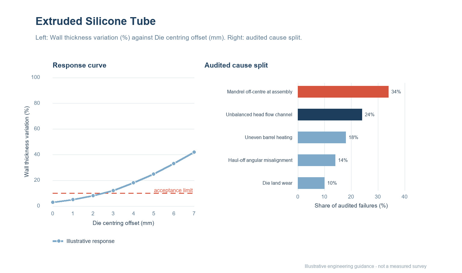
The left panel shows wall thickness variation (%) as die centring offset (mm) increases: the response rises from 3 to 42 on the illustrative 0–100 scale. The dashed line at 10 marks a proposed acceptance limit, not a universal standard. Move that line only after the test method and the sample plan have been agreed, otherwise two suppliers can both be compliant and still deliver different parts.
Read the shape rather than a single point. A curve that changes quickly near the limit is more sensitive to ordinary process noise than one that approaches it gradually, and that difference should be reflected in how tightly the setting is controlled and how often it is checked.
Where the causes actually sit
The right panel of Figure 1 splits audited failures of this type into five groups. The percentages are illustrative engineering guidance for prioritising an investigation, not a measured survey and not a prediction for your line.
| Cause | Illustrative share | First check |
|---|---|---|
| Mandrel off-centre at assembly | 34% | Cut a ring at start-up and map wall thickness at eight clock positions. |
| Unbalanced head flow channel | 24% | Clock-mark the thin side and confirm it does not rotate along the length. |
| Uneven barrel heating | 18% | Check die and mandrel concentricity with a feeler gauge before the run. |
| Haul-off angular misalignment | 14% | Review barrel zone temperatures for a left-right spread. |
| Die land wear | 10% | Re-measure after a die clean to separate wear from setting error. |
Table 2. Cause split and the corresponding first check. Shares are indicative and sum to 100.
Mandrel off-centre at assembly accounts for roughly 34% of the illustrative split. Cut a ring at start-up and map wall thickness at eight clock positions. Start here before authorising a material or tooling change, because it is the fastest explanation to confirm or eliminate.
Unbalanced head flow channel accounts for roughly 24% of the illustrative split. Clock-mark the thin side and confirm it does not rotate along the length. Start here before authorising a material or tooling change, because it is the fastest explanation to confirm or eliminate.
Uneven barrel heating accounts for roughly 18% of the illustrative split. Check die and mandrel concentricity with a feeler gauge before the run. Start here before authorising a material or tooling change, because it is the fastest explanation to confirm or eliminate.
Checks before sign-off
In practice the sequence below is cheaper to run than a root-cause debate after a rejected delivery.
- Cut a ring at start-up and map wall thickness at eight clock positions.
- Clock-mark the thin side and confirm it does not rotate along the length.
- Check die and mandrel concentricity with a feeler gauge before the run.
- Review barrel zone temperatures for a left-right spread.
- Re-measure after a die clean to separate wear from setting error.
Keep a retained reference sample beside every result. When a batch is disputed, the comparison that settles it is almost always between the retained part and the current one under the same method, not between either part and a number on a drawing. Record the instrument, the operator, the conditioning time and the position on the part or sheet for each reading.
Writing it into the specification and the evidence pack
Define wall-thickness variation across eight clock positions on a start-up ring and require the thin side to be recorded before the run is released.
Write the requirement as a behaviour at a stated condition, not as a brand of material or a machine setting. State the test method, the conditioning, the sample plan and the rule for deciding a pass. Where a document is needed, ask the supplier for documentation that covers the actual construction and check its scope against your own market before approval; a document for the base material alone does not describe the finished part you are buying.
At first-article approval, freeze the drawing revision, the material and colour identification, the process window, the tool and cavity identification, and the inspection method. Any later change to grade, site, tool, or window should trigger a new first article rather than a paper waiver. Keep retained samples from the approved lot and from each production lot so that a future comparison is possible.
| Evidence item | What it must show |
|---|---|
| Approved drawing and revision | The exact geometry and tolerances the decision applies to |
| Material and colour identification | Grade, supplier, colour reference and any declared recycled content |
| Process window and change log | The agreed settings and any deviation since approval |
| Inspection record and retained samples | Method, conditions, results and a physical reference from the same lot |
Table 3. Minimum evidence pack for a first-article decision and a later batch dispute.
All ranges in this article are illustrative engineering guidance rather than measured data. Treat them as a starting agenda for a process trial, not as a certificate for a batch that has not been run.
Questions buyers ask
Is this a material problem or a process problem?
Wall distribution is set by the annular gap between die and mandrel. If the mandrel sits off-centre or the flow channel is unbalanced, the gap is wider on one side and the extrudate leaves the die with an eccentric wall that downstream sizing cannot correct. It is worth separating the two before a supplier changes a grade: hold the material constant for one controlled run, then move one setting at a time. If the symptom follows the setting, the material was never the cause.
Can die-to-mandrel concentricity be traded against cycle time?
Only within the window stated in Table 1, and only with a recorded trial. Offset beyond this fixes an eccentric wall for the whole run A faster cycle that sits outside the window usually moves the failure downstream, where it costs more to find.
What should be recorded at incoming inspection?
Keep the measurement, the method, the sample identity and the conditions together. Cut a ring at start-up and map wall thickness at eight clock positions. A result without its conditions cannot be compared with a later batch.
Does a change of extruded tube require re-approval?
Treat any change to material grade, tool, site or process window as a change that needs a new first-article decision. For silicone rubber work the drawing alone is not enough; the process route is part of what was approved.
How many samples are enough for a first-article decision?
There is no universal number. Sample across cavities, lanes, sheet positions or reel lengths so that the spread is visible, not just the average. Agree the sample plan and the acceptance rule with the supplier before the trial starts.
What belongs in the evidence pack?
The approved drawing and revision, the material and colour identification, the process window, the inspection method and results, the retained reference samples, and documentation covering the actual construction. Ask the supplier to state the scope of each document and check it against your own market.
Seeing this on a current silicone rubber job?
Send the drawing, the material and grade, the process window you are running, and the point in the cycle or the shelf life where the fault appears. We will help you separate a material question from a process question and a specification question before anyone changes a tool.
Continue reading
- Silicone Tube Extrusion: Cold Feed, Hot Cure and Tight Tolerance
- Silicone Extrusion: Curing a Profile That Cannot Hold Its Own Shape
- Die Swell: Why the Profile Leaves Bigger Than the Die
- Cable Concentricity: The Measurement That Predicts Failure
- Inline Gauging on an Extrusion Line: What It Catches and What It Misses

 EN
 ES
 FR
 DE
 PT
 AR
 RU
 JA
 KO
 IT
 NL
 TR
 PL
 ID