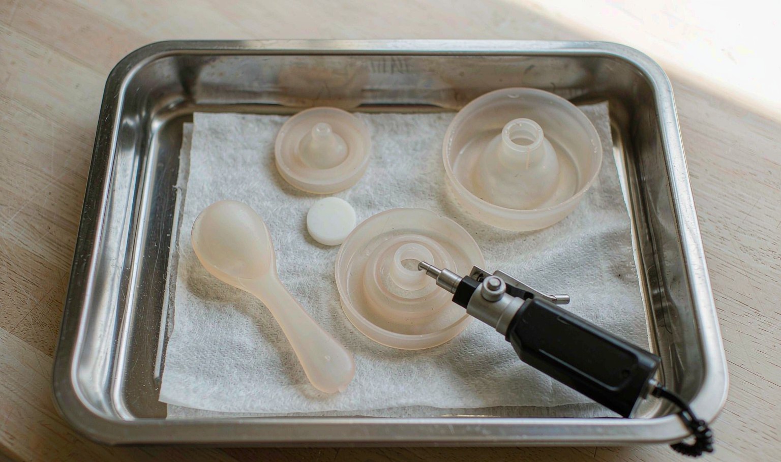
A moulded gear runs quietly at first, then scores its mating face; the tooth flanks show fibre-rich streaks aligned with the flow.
What the failure looks like on the line
Industrial moulded parts are usually specified by a drawing and a duty cycle, not by appearance, which is why a dimensionally conforming part can still fail in service.
Under load the gear tooth flank develops a dull, fibrous streak and the mating metal wears faster than expected. The part measures within tolerance but the surface is visibly directional at the gate end.
During filling, glass fibres orient along the flow and the skin layer is resin-rich while the core is fibre-rich; where flow-front hesitation or a weld region interrupts orientation, fibre bundles break through the surface. Exposed fibre ends are abrasive against the mating metal and act as stress raisers at the tooth root. Orientation also makes shrinkage anisotropic, so roundness drifts with the fill pattern.
Start with the failure as it is reported, not with the parameter that is easiest to measure. On a buyer's specification this distinction matters: a part can measure inside tolerance and still fail in use, because the drawing records geometry while the complaint records behaviour. Glass fibre content is usually the first value both sides compare, and it is also the one most often quoted without the conditions attached to it.
The process window that decides it
Four variables move this result more than the rest. The ranges below are illustrative engineering guidance for a first discussion; confirm them on your own tool, material grade and part geometry before they become contract terms.
| Variable | Typical window | What fails outside it |
|---|---|---|
| Glass fibre content | 25-35 % by mass | Above the window fibres crowd the skin and break through |
| Injection speed | 50-90 mm/s | Too high a shear aligns fibres strongly and raises read-through |
| Mould temperature | 80-110 C | A cold tool freezes a thin resin skin before fibres are buried |
| Holding pressure | 70-100 MPa | Low holding leaves fibre-rich regions unsustained at the surface |
Table 1. Starting window for a joint process trial. Values are engineering guidance, not a measured survey.
Glass fibre content is typically held at 25-35 % by mass. Above the window fibres crowd the skin and break through Record it together with the measurement point and the moment in the cycle; a single number without a location is not a process setting.
Injection speed is typically held at 50-90 mm/s. Too high a shear aligns fibres strongly and raises read-through When this drifts, the symptom usually appears at one cavity, one sheet position or one lane before it appears across the whole batch.
Mould temperature is typically held at 80-110 C. A cold tool freezes a thin resin skin before fibres are buried A change here is cheap during a trial and expensive after tooling release, so treat it as a controlled variable with a documented re-approval.
Holding pressure is typically held at 70-100 MPa. Low holding leaves fibre-rich regions unsustained at the surface Put it on the change-control list, otherwise an unannounced material or setting substitution will be mistaken for ordinary process noise.
Reading the response curve
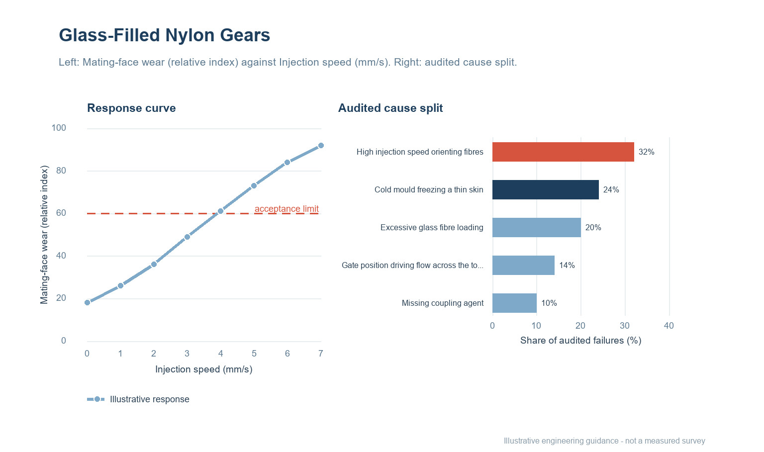
The left panel shows mating-face wear (relative index) as injection speed (mm/s) increases: the response rises from 18 to 92 on the illustrative 0–100 scale. The dashed line at 60 marks a proposed acceptance limit, not a universal standard. Move that line only after the test method and the sample plan have been agreed, otherwise two suppliers can both be compliant and still deliver different parts.
Read the shape rather than a single point. A curve that changes quickly near the limit is more sensitive to ordinary process noise than one that approaches it gradually, and that difference should be reflected in how tightly the setting is controlled and how often it is checked.
Where the causes actually sit
The right panel of Figure 1 splits audited failures of this type into five groups. The percentages are illustrative engineering guidance for prioritising an investigation, not a measured survey and not a prediction for your line.
| Cause | Illustrative share | First check |
|---|---|---|
| High injection speed orienting fibres | 32% | Section a tooth and inspect the flank under magnification for exposed fibre ends. |
| Cold mould freezing a thin skin | 24% | Compare roundness measured in flow direction and transverse to it. |
| Excessive glass fibre loading | 20% | Map gate position against the location of the fibrous streaks. |
| Gate position driving flow across the tooth | 14% | Run a short-shot series to see where fibre orientation changes across the tooth. |
| Missing coupling agent | 10% | Check the declared fibre content and coupling-agent package against the compound data. |
Table 2. Cause split and the corresponding first check. Shares are indicative and sum to 100.
High injection speed orienting fibres accounts for roughly 32% of the illustrative split. Section a tooth and inspect the flank under magnification for exposed fibre ends. Start here before authorising a material or tooling change, because it is the fastest explanation to confirm or eliminate.
Cold mould freezing a thin skin accounts for roughly 24% of the illustrative split. Compare roundness measured in flow direction and transverse to it. Start here before authorising a material or tooling change, because it is the fastest explanation to confirm or eliminate.
Excessive glass fibre loading accounts for roughly 20% of the illustrative split. Map gate position against the location of the fibrous streaks. Start here before authorising a material or tooling change, because it is the fastest explanation to confirm or eliminate.
Checks before sign-off
In practice the sequence below is cheaper to run than a root-cause debate after a rejected delivery.
- Section a tooth and inspect the flank under magnification for exposed fibre ends.
- Compare roundness measured in flow direction and transverse to it.
- Map gate position against the location of the fibrous streaks.
- Run a short-shot series to see where fibre orientation changes across the tooth.
- Check the declared fibre content and coupling-agent package against the compound data.
Keep a retained reference sample beside every result. When a batch is disputed, the comparison that settles it is almost always between the retained part and the current one under the same method, not between either part and a number on a drawing. Record the instrument, the operator, the conditioning time and the position on the part or sheet for each reading.
Writing it into the specification and the evidence pack
Surface finish on functional tooth flanks shall be compared with an agreed limit sample under defined lighting; flanks showing fibre read-through beyond the sample are rejectable, and roundness shall be reported in both flow and transverse directions.
Write the requirement as a behaviour at a stated condition, not as a brand of material or a machine setting. State the test method, the conditioning, the sample plan and the rule for deciding a pass. Where a document is needed, ask the supplier for documentation that covers the actual construction and check its scope against your own market before approval; a document for the base material alone does not describe the finished part you are buying.
At first-article approval, freeze the drawing revision, the material and colour identification, the process window, the tool and cavity identification, and the inspection method. Any later change to grade, site, tool, or window should trigger a new first article rather than a paper waiver. Keep retained samples from the approved lot and from each production lot so that a future comparison is possible.
| Evidence item | What it must show |
|---|---|
| Approved drawing and revision | The exact geometry and tolerances the decision applies to |
| Material and colour identification | Grade, supplier, colour reference and any declared recycled content |
| Process window and change log | The agreed settings and any deviation since approval |
| Inspection record and retained samples | Method, conditions, results and a physical reference from the same lot |
Table 3. Minimum evidence pack for a first-article decision and a later batch dispute.
All ranges in this article are illustrative engineering guidance rather than measured data. Treat them as a starting agenda for a process trial, not as a certificate for a batch that has not been run.
Questions buyers ask
Is this a material problem or a process problem?
During filling, glass fibres orient along the flow and the skin layer is resin-rich while the core is fibre-rich; where flow-front hesitation or a weld region interrupts orientation, fibre bundles break through the surface. Exposed fibre ends are abrasive against the mating metal and act as stress raisers at the tooth root. Orientation also makes shrinkage anisotropic, so roundness drifts with the fill pattern. It is worth separating the two before a supplier changes a grade: hold the material constant for one controlled run, then move one setting at a time. If the symptom follows the setting, the material was never the cause.
Can glass fibre content be traded against cycle time?
Only within the window stated in Table 1, and only with a recorded trial. Above the window fibres crowd the skin and break through A faster cycle that sits outside the window usually moves the failure downstream, where it costs more to find.
What should be recorded at incoming inspection?
Keep the measurement, the method, the sample identity and the conditions together. Section a tooth and inspect the flank under magnification for exposed fibre ends. A result without its conditions cannot be compared with a later batch.
Does a change of industrial require re-approval?
Treat any change to material grade, tool, site or process window as a change that needs a new first-article decision. For injection moulding work the drawing alone is not enough; the process route is part of what was approved.
How many samples are enough for a first-article decision?
There is no universal number. Sample across cavities, lanes, sheet positions or reel lengths so that the spread is visible, not just the average. Agree the sample plan and the acceptance rule with the supplier before the trial starts.
What belongs in the evidence pack?
The approved drawing and revision, the material and colour identification, the process window, the inspection method and results, the retained reference samples, and documentation covering the actual construction. Ask the supplier to state the scope of each document and check it against your own market.
Seeing this on a current injection moulding job?
Send the drawing, the material and grade, the process window you are running, and the point in the cycle or the shelf life where the fault appears. We will help you separate a material question from a process question and a specification question before anyone changes a tool.
Continue reading
- Glass-Filled Nylon Injection Molding: Fibre Breakage, Warp and Tool Wear
- Injection Speed Profiling: The Fastest Fill Is Not the Cheapest One
- Mould Flow Analysis: What the Simulation Gets Right and What It Misses
- Warpage in Injection Molding: Differential Shrinkage From Gate to Last Point
- Wall Thickness Design: The Single Most Consequential Decision

 EN
 ES
 FR
 DE
 PT
 AR
 RU
 JA
 KO
 IT
 NL
 TR
 PL
 ID