

What core shift actually is
Core shift is the sideways movement of one half of the mold relative to the other while the cavity is under pressure. The core is the male half that forms the inside of the part, and it is held between the cavity plate and the support plate.
That sandwich is the problem. The cavity plate is bolted to the platen and barely moves. The support plate sits on the ejector side, and the ejector system pushes against it every cycle. Between those two, the core is held by shoulders, dowels and pins, and it carries the full cavity pressure on its back face.
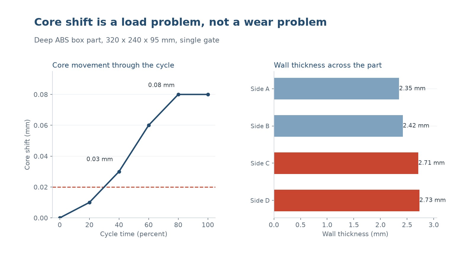
When the cavity pressure is not balanced, the core leans. A few tenths of a millimetre of lean is invisible on a flat panel and obvious on a deep box, where it changes one wall thickness while leaving the other alone.
This is why core shift is usually diagnosed late. The part still fills, the dimensions still look plausible on the first article, and the defect only shows up when someone measures wall thickness on a sectioned part.
What pushes the core sideways
Uneven pressure across the cavity face is the root cause. A long rectangular part filled from one end produces a pressure gradient across the length, and the high pressure region pushes the core harder than the low pressure region.
The second cause is asymmetric cooling. If the core is cooled on one side more aggressively than the other, the two halves shrink differently and the mold opens asymmetrically under the clamp.
The third is a support plate that is not stiff enough, or a core shoulder with no land area. A core with short locating shoulders can walk sideways every cycle under the cyclic load of injection and ejection.
The fourth, and the one that catches people, is that the defect may not be in the mold at all. A misaligned machine platen or a tie bar that is not square to the parting line produces the same symptom. Diagnose the mold and the machine before you start cutting steel.
How to measure it
Do not measure the part. Measure the mold. The part tells you the total effect, but not which half moved.
The simplest method is to put a dial indicator on the core top and read it at three points: empty, at peak cavity pressure, and after the mold has opened. Any reading that changes as the cycle runs tells you the core is moving under load.
A second method is witness marking. Lightly scribe a line across the core and the cavity plate before the shift, then run a few hundred cycles and look at the offset. This tells you the magnitude and whether it is stable or creeping.
For the part itself, section it. Cut a cross-section through the region you think is off, and measure wall thickness at four or five points around the perimeter. A consistent asymmetry around one axis points to core shift. A thickness that tapers from one end to the other points to uneven filling instead, which is a different problem with a different fix.
Mold design changes that work
The most effective change is to increase the core support area. A longer shoulder land distributes the load over more of the core back face and cuts the bending moment. On the example mold, going from a 30 mm shoulder to a 55 mm shoulder reduced measured core shift by roughly 60 percent.
The second is to close the cavity from both ends rather than one. Two gates at opposite ends of a long part roughly halve the pressure gradient, and the balance is even better if the gates are fed at matched rates.
The third is to put a support directly behind the back shot area, where the pressure is highest. A support pad under the runner landing transfers the peak load into the support plate instead of letting the core take it as a bending moment.
The fourth is to stop the ejector system from becoming the lever that moves the core. Ejector pins that bear against a thin core shoulder act like a hydraulic jack on that shoulder. Supporting the ejector plate properly and keeping the pins short reduces the asymmetric load.
| Karena | Symptom | Correction |
|---|---|---|
| Uneven cavity pressure | Wall thin on one axis only | Balance gate flow, use two gates |
| Asymmetric cooling | Shift changes with cycle count | Equalise cooling circuits |
| Short core shoulders | Shift on every cycle, stable | Lengthen shoulder land |
| Ejector pin reaction | Shift grows with part depth | Support ejector plate, shorten pins |
| Platen misalignment | Shift on all tools on the machine | Re-align platen, check tie bars |
Table 1 — Core shift causes and what to change.
What it costs to leave it alone
The direct cost is scrap. A deep box with a 6 percent wall difference has a minimum wall somewhere, and if that minimum is already close to the design limit, whole batches fail.
The indirect cost is worse. A core that moves under load moves differently every cycle as the mold warms up and the steel expands. That means a slow drift in the part dimensions over a shift, and an out-of-spec window that opens and closes without a clear cause.
There is also a wear consequence. A core that is leaning against its shoulders during every shot is running on a small contact area, and that contact area wears. After a few hundred thousand shots the shoulders are no longer round, and the problem grows on its own.
And the ones nobody costs out are the field failures. A molded enclosure with one wall 6 percent thin is often still fine. A molded part with a thin wall that is also the sealing surface is not, and that combination is only discovered when the customer complains.
A practical order of work
First, rule out the machine. Put the dial indicator on the core, cycle it empty, and confirm that the core does not move when the screw is not injecting. If it moves, the problem is platen alignment or ejector return, and no mold work will fix it.
Second, confirm the direction. Section a part and measure the wall at four points. A thin wall on one side means the core leaned toward the thick side. Once you know the direction, the correction is direction-specific and you are no longer guessing.
Third, look for the loading asymmetry in the mold. A support plate that is thinner than the cavity plate, a core with three locating features instead of four, or a gate that fills one end long before the other are all visible in the tool.
Fourth, make one change at a time and re-measure with the same indicator setup. Core shift problems respond to changes in the mold steel, the cooling circuit and the gate layout, and three changes at once gives you no information about which one worked.
| Langkah | Tindakan | Pass criterion |
|---|---|---|
| 1 | Dial indicator on core, empty cycle | Less than 0.02 mm movement |
| 2 | Section and measure wall at 4 points | Asymmetry below 2 percent |
| 3 | Verify gate fill balance | Both gates fill within 10 percent |
| 4 | Check cooling circuit symmetry | Both sides within 3 C |
| 5 | Re-measure after one change | Shift reduced by half or more |
Table 2 — Diagnostic sequence for core shift.
What is core shift in injection molding?
It is the sideways movement of one half of the mold relative to the other while the cavity is filled. The core leans toward the thicker wall and the part comes out with an asymmetric wall thickness.
How much core shift is acceptable?
Less than 0.02 mm of core movement at peak cavity pressure. Above that, a deep box part typically shows a 3 to 6 percent wall difference, which is usually outside normal part tolerance.
Can a tight shot reduce core shift?
It reduces the symptom, not the cause. Lower peak pressure lowers the bending moment on the core, but the part then needs a higher holding pressure or longer hold to control shrink, and you may end up with a different defect.
Is core shift a mold problem or a machine problem?
Usually a mold problem, but always rule out the machine first. Platen misalignment and tie bars that are not square produce an identical symptom and will make every mold you run on that machine look defective.
Why does the defect get worse over a shift?
As the mold warms, the steel expands and the cooling circuit settles into equilibrium. If the two halves cool differently, the core leans progressively further as the temperature difference grows.
Can a core support plate fix core shift?
Lengthening the shoulder land that locates the core is usually the single most effective change. A 30 mm shoulder extended to 55 mm can cut measured shift by roughly 60 percent on a deep box part.
Parts coming off centre?
Send the part, the material and the tool dimensions. We will tell you whether the cause is in the mold, the machine or the process window, and what has to change.







 ID
 EN
 ES
 FR
 DE
 PT
 AR
 RU
 JA
 KO
 IT
 NL
 TR
 PL
