
Air is the last thing to leave
A cavity is full of air before it is full of plastic. The plastic arrives at the gate at a few hundred bar and pushes the air ahead of it, and the air has to leave through the parting line, through a vent, or through the ejector pin clearances. If it cannot leave, it compresses.
Compressed air gets hot. A cavity that fills in half a second and cannot vent will compress the air at the end of the flow to a pressure that raises its temperature several hundred degrees, and the plastic at that point scorches. That is a burn: a black or brown patch, always at the last place to fill, always with a sharp edge on the upstream side.
The confusing part is that a burn looks like a material problem and is a tool problem. The first response is usually to drop the melt temperature or slow the injection, both of which reduce the burn and both of which cost cycle. A vent costs nothing after the tool is cut and nothing to run.
Depth is a window between two failures
A vent has to be shallow enough that the plastic does not enter it and deep enough that the air can. Those two requirements produce two curves that cross, and the crossing is the working depth.
At 0.005 mm of vent depth the burn rate is 24 percent, because the vent is effectively closed. At 0.010 it is 11, at 0.015 it is 4.2, at 0.020 it is 1.1, at 0.025 it is 0.5 and at 0.030 it is 0.3. The burn curve falls steeply and then flattens.
The flash curve does the opposite. At 0.005 mm it is 0.1 percent, at 0.015 it is 0.4, at 0.020 it is 0.9, at 0.025 it is 2.4 and at 0.030 it is 7.8. It rises slowly and then steeply, because once the gap is wide enough for the melt to enter, the entry is fast.
The two curves cross at about 0.021 mm, and that is why the standard vent depth for most commodity plastics is 0.02 mm. It is not a rule of thumb, it is the intersection of two failure modes, and it moves with the material: a low viscosity grade needs a shallower vent, a glass filled one a slightly deeper one because the glass does not flow into a 0.02 mm gap.

Position beats depth
Once the depth is in the window, the next gain comes from where the vents are. On the same total vent area, one vent gives a burn rate of 6.2 percent. Two give 3.1, four give 1.4, six give 0.9 and eight give 0.7.
The reason is that air does not flow sideways along a parting line. It leaves where the flow front pushes it, which is the last point to fill, and if that point has no vent the air has to travel to find one. A long thin cavity with a vent at one end is a cavity with a burn at the other end, no matter how deep the vent is.
Which means the vent layout comes from a fill simulation or from a short shot, not from a habit. The short shot is the cheap version: run the tool at 80 percent fill, look at where the flow front stops, and put a vent there. Repeat at 90 and 95 percent, because the last place to fill moves as the pressure rises.
Where the vents have to go
The end of the flow path is the first place. On a simple part that is the far edge from the gate; on a part with ribs it is the end of each rib, because a rib fills last and its tip is a dead end.
A weld line is the second. Two flow fronts meeting trap the air between them, and a weld line with no vent is a weld line with a burn in it. A vent at the weld line also improves the weld strength, because air in the weld is what makes it weak.
A blind boss or a deep pocket is the third, and it is the one most often missed. A boss fills from the bottom and the air has nowhere to go, so a small vent at the top of the boss is worth more than a large one on the parting line.
The fourth is the gate itself, on the opposite side. Air can be pushed back through the sprue if the machine allows it, but a vent at the far end of the runner is what stops the air being pushed into the cavity in the first place.
The four kinds of vent
A parting line vent is a shallow groove milled into the parting face, running from the cavity edge to the outside of the block. It is the cheapest, it is the easiest to clean, and it is the one that wears: the parting face is what takes the clamp load, and a groove in it closes up over time.
An ejector pin clearance is a vent that already exists. A pin in a hole with 0.02 to 0.03 mm of clearance vents the cavity at no cost, which is why a part with a burn at an ejector pin is a part with a blocked pin.
A porous steel insert is a block of sintered metal set into the cavity wall. Air passes through the metal, the plastic does not, and it vents an area rather than a line. It is used on a deep blind pocket and on a part where a groove is impossible, and it clogs and needs cleaning.
A vacuum system pulls the air out before the shot. It is the most effective and the most expensive, it needs a seal around the cavity and a valve, and it is used where the other three cannot do the job: a very thin wall, a very fast fill, or a part with nowhere to put a groove.
| Тип | Depth | Cleaning | Используйте |
|---|---|---|---|
| Parting line groove | 0.02 mm | Easy | Default |
| Ejector pin clearance | 0.02-0.03 mm | With the pin | Free, if the pin is there |
| Porous steel insert | Материал | Difficult | Blind pocket, deep boss |
| Vacuum | Not applicable | Seal check | Thin wall, fast fill |
Table 1 — Vent types and where each one is the right answer
Vents clog, and that is the maintenance item
A 0.02 mm groove is 20 microns wide. It fills with plasticiser, with mould release, with a film of the polymer itself, and with the dust that is in every workshop. The burn comes back, slowly, and the first response is usually to raise the injection speed, which makes it worse.
The cleaning is a brass scraper and a solvent, on a schedule rather than on a symptom. A vent that is checked every shift and cleaned when it needs it never produces a burn; a vent that is cleaned when the parts go black produces a burn every few months and a scrapped batch with it.
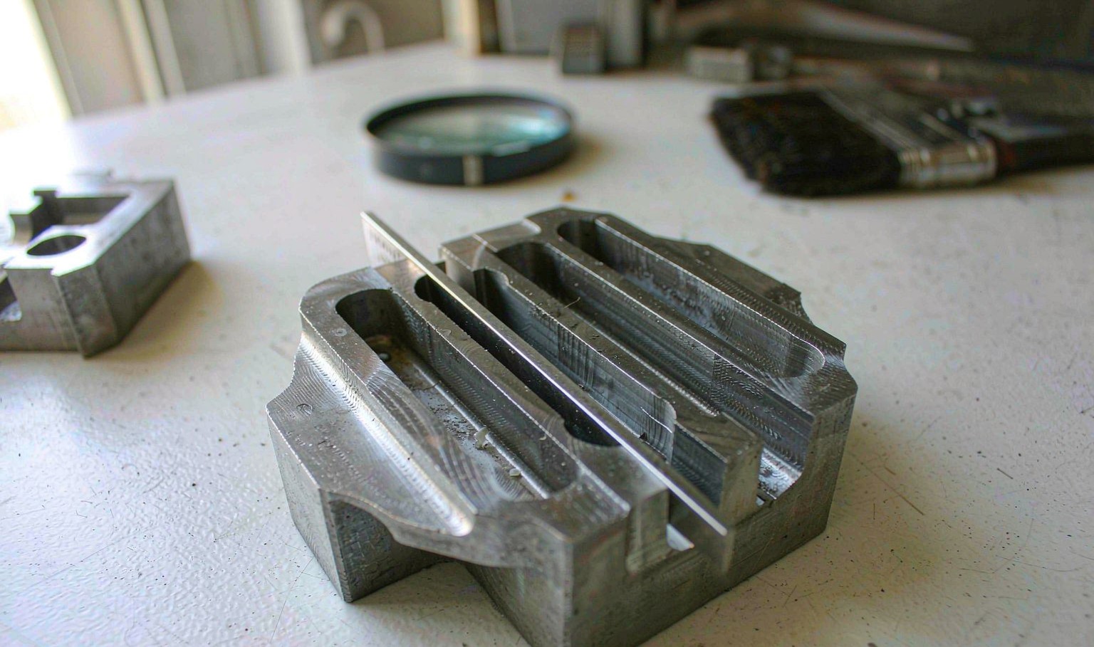
The measurement is the feeler gauge in the photo. A 0.02 mm blade should pass and a 0.03 mm blade should not. If the 0.02 blade will not pass, the vent is closed; if the 0.03 passes, the vent has worn and the flash is on its way.
| Symptom | Причина | Fix |
|---|---|---|
| Burn at the last point to fill | Blocked or missing vent | Clean, or add a vent |
| Flash along the parting line | Vent worn too deep | Re-cut, or move the vent |
| Burn at a weld line | No vent at the meeting point | Add a vent there |
| Burn at a boss | Blind pocket | Porous insert or a vent at the top |
Table 2 — Reading the symptom back to the vent
How deep should a mould vent be?
0.02 mm for most commodity plastics, because that is where the burn curve and the flash curve cross. Low viscosity grades want less, glass filled grades a little more.
Why does my part burn at the last place to fill?
Because the air has nowhere to go and it is being compressed. A vent at that point, not a lower melt temperature, is the fix.
Is one big vent as good as several small ones?
No. On the same total area, one vent gives a 6.2 percent burn rate and eight give 0.7 percent, because air leaves where the flow front pushes it.
Can ejector pins vent a mould?
Yes, through their clearance, at 0.02 to 0.03 mm. A burn at an ejector pin usually means the pin or the hole is blocked.
How do I check a vent?
With a feeler gauge. A 0.02 mm blade should pass and a 0.03 mm blade should not; if the 0.02 will not pass the vent is closed.
When is vacuum venting worth it?
On a very thin wall, a very fast fill, or a part with nowhere to put a groove. It is the most effective and the most expensive option.
A part that burns at the end of fill, or flashes at the parting line?
Send the part, the gate position and a short shot. We will tell you where the vents belong and what depth the material needs.
Continue reading
- Gate Design in Injection Molding: Where the Plastic Enters
- Flash in Injection Molding: Where It Comes From and How to Stop It
- Ejection System Design: Pins, Sleeves, Strippers and the Marks They Leave
- Short Shot in Injection Molding: When the Cavity Does Not Fill
- Custom Injection Molding: Tooling, Tolerances and Volume




 RU
 EN
 ES
 FR
 DE
 PT
 AR
 JA
 KO
 IT
 NL
 TR
 PL
 ID
