

Thin walls are a pressure problem
The usual description of thin-wall moulding is that it is about cooling, because a thin wall cools fast and the cycle is short. That is the benefit. The problem is getting the melt to the end of the cavity before it freezes, and that is a pressure problem.
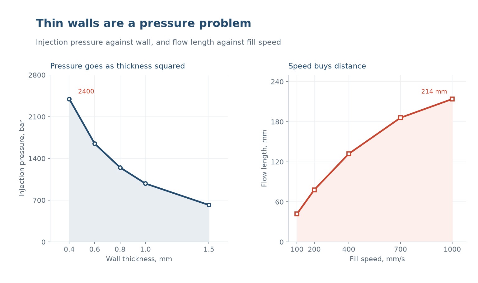
Pressure drop along a flow path goes roughly as the inverse square of thickness, and in practice worse, because the frozen layer grows as the melt advances and narrows the flow channel further. Taking the wall from 1.5 mm to 0.4 mm takes the required pressure from 620 bar to 2,400 bar, which is a factor of nearly four.
That number is the reason thin-wall machines exist. A standard machine tops out around 1,500 to 2,000 bar of injection pressure; a thin-wall machine has a higher-rated hydraulic system, a stronger clamp, and a screw and barrel designed for the pressure. Running thin-wall work on a standard machine means running at the edge of what it can do, all day.
Speed buys distance, with diminishing returns
If pressure is the constraint, the counter-intuitive fix is to fill faster. A faster fill means less time for the frozen layer to grow, so the effective flow channel stays open longer and the melt reaches further before it stalls. Flow length goes from 42 mm at 100 mm/s to 78 at 200, 132 at 400, 186 at 700 and 214 at 1,000.
The returns diminish because the relationship is not linear in speed. Doubling from 100 to 200 buys 36 mm; doubling again from 500 to 1,000 buys about 30 mm. Past about 700 mm/s the gain per increment is small and the problems per increment are not.
The problems are shear and gate wear. At 1,000 mm/s the shear rate in a small gate is high enough to degrade the polymer, and the gate erodes. A thin-wall tool with a small gate run at high speed has a gate that is a consumable, and that is a maintenance line item nobody budgets.
What the machine has to be able to do
Three things, beyond pressure. The first is injection rate: filling a 0.4 mm wall at 1,000 mm/s needs an accumulator or a high-flow valve, because the screw cannot accelerate fast enough on its own. The second is clamp stiffness, because a thin part flashes at a lower pressure than a thick one and the platens deflect under the injection load.
The third is screw recovery. A thin-wall part is light, so the shot is small, and a small shot on a large screw means a short stroke and poor repeatability. Thin-wall machines use a smaller screw at higher pressure rather than a large screw at low pressure, and that is the opposite of what a general-purpose machine is set up for.
Cooling is where the cycle is won, and it is the one part of the process that behaves the way people expect. A 0.4 mm wall is mostly surface, so it cools in a second or two and the cycle is dominated by the robot and the ejection rather than by the mould.
| Requirement | Standard machine | Thin-wall machine |
|---|---|---|
| Injection pressure | 1,500-2,000 bar | 2,500 bar and above |
| Injection rate | Screw-limited | Accumulator assisted |
| 나사 | Large, long stroke | Small, short stroke |
| Clamp stiffness | General | High, low deflection |
| Cycle | Cooling dominated | Robot and ejection dominated |
Table 1 — What separates a thin-wall machine from a general one
The tool is where the limits are set
Gate design decides most of it. A thin-wall part needs a gate large enough to pass the flow at high speed without excessive shear, and short enough that the pressure drop across it is small. A hot runner with a valve gate gives the fastest fill and the best control, at a tool cost that only makes sense at volume.
Venting becomes critical because the fill is fast and the air has nowhere to go. A thin-wall cavity filled in a fraction of a second compresses the air ahead of the front, and inadequate venting shows up as a burn mark at the last point to fill, which is often mistaken for a temperature problem.
Ejection is the third. A thin wall is flexible and it will drag on the core if the draft is marginal. Thin-wall parts need more draft than thick ones, not less, because the part deflects under ejection rather than sliding off.
Where the process stops
The practical floor for wall thickness in production is around 0.3 to 0.4 mm for polypropylene and polystyrene, and higher for engineering resins. Below that the flow length becomes so short that the part has to be gated in multiple places, and the weld lines become the weak point.
The other limit is the material. High flow grades exist precisely for this, with a lower molecular weight and a narrower molecular weight distribution, and they are more brittle than the standard grades. A thin-wall part in a high-flow grade is more likely to crack at a snap fit than the same part in a standard grade.
And there is a limit on what the part can be asked to do. A 0.4 mm wall is a good container and a poor structural member. Thin-wall design works when the geometry provides the stiffness through ribs and shape, not when the wall is expected to carry load on its own.
When it is the right answer
It is the right answer for high-volume packaging: tubs, lids, cups, trays and containers, where the material saving per part is small but the part count is enormous. It is also right where the part must be light, which is usually the same case.
It is the wrong answer for low volume, because the tool and the machine time have to be paid for; for thick sections, where the process has nothing to offer; and for parts that need to be strong in the wall rather than in the geometry.
| Case | Wall | Verdict |
|---|---|---|
| Food tub, 10 million a year | 0.4-0.6 mm | Ideal |
| Paint pail lid | 0.8 mm | Good |
| Housing with ribs | 1.2-1.5 mm | Possible, usually not worth it |
| Structural bracket | 2 mm and above | Wrong process |
| Prototype, 5,000 parts | Any | Wrong economics |
Table 2 — Where thin-wall moulding fits
What is the thinnest wall that can be moulded reliably?
Around 0.3 mm for polypropylene in a well-gated tool, and 0.4 mm is a realistic production figure. Below that the flow length is very short and the part needs multiple gates and weld lines.
Why does higher speed help rather than hurt?
Because the frozen layer has less time to grow, so the effective flow channel stays open and the melt reaches further. The limit is shear degradation at the gate, not the cavity.
Can a standard machine run thin-wall work?
It can, at its pressure limit and at a lower speed, which means a longer fill and a shorter flow length. For occasional work that is fine; for continuous production the machine is the constraint.
Does a thin-wall tool need more cooling?
Less, in the sense that the part gives up its heat quickly. It needs good cooling uniformity, because a thin part warps easily and the cycle is short enough that any imbalance shows immediately.
Why do thin-wall parts flash more easily?
Because the cavity pressure is high and the wall is thin, so the clamp has to resist a higher separating force relative to its size. A marginal clamp shows up as flash at the parting line on the cavity side.
Is a high-flow grade always needed?
For walls below about 0.6 mm, usually yes. High-flow grades are more brittle, so the part design has to avoid sharp notches and snap fits that rely on ductility.
A thin-wall part with a fill problem?
Send the wall section, the flow length and the material. We will tell you whether the pressure is achievable, whether a gate change fixes it, and what machine the part actually needs.
Continue reading
- Injection Speed Profiling: Where the Speed Actually Goes
- Cooling Time Optimization: The Part Is Cold When It Leaves
- Injection Cycle Time Reduction: Where the Seconds Actually Are
- Sink Marks in Injection Molding: Pack, Gate and the Shrink That Shows
- Custom Injection Molding: Tooling, Tolerances and Volume




 KO
 EN
 ES
 FR
 DE
 PT
 AR
 RU
 JA
 IT
 NL
 TR
 PL
 ID
