
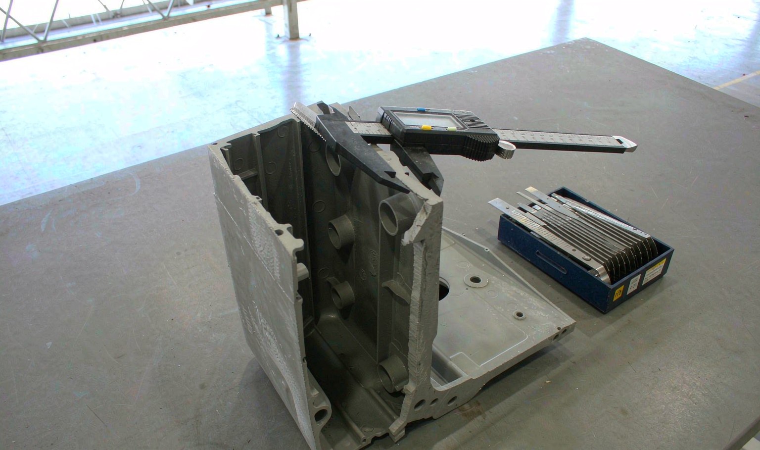
One number sets the machine, the tool and the price
Wall thickness decides the shot weight, the injection pressure, the clamp force, the cooling time, the cycle time, the shrink, the warpage and the price. It is the first number on the drawing and the last one anybody wants to change, because changing it invalidates everything downstream.
It is also the number most often set by copying a previous part. A wall that was right for a 200 mm housing is not right for a 60 mm one, and a wall that was right in ABS is not right in PC, because the two polymers have different flow lengths and different shrinkages.
The reason it dominates is that every other quantity is a power of the wall. Cooling time goes roughly with the square, stiffness with the cube, weight linearly. A small change in the wall is a large change in everything else.
That is why the design conversation is worth having early. Once the tool is cut, a wall change is a new cavity insert, and the cost of the conversation moves from an hour of engineering to a month of tooling.
Cooling time goes with the square
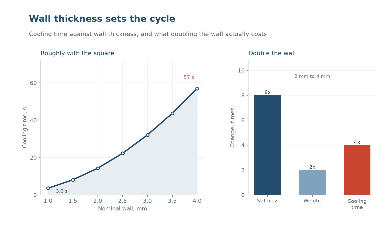
Cooling is conduction through the wall, and the time for heat to diffuse out of a slab scales with the square of its thickness. Double the wall and the cooling time quadruples, not doubles.
Measured on a PP part with a 40 C mould and a 200 C melt, the cooling time was 3.6 seconds at 1.0 mm, 8.1 at 1.5, 14.3 at 2.0, 22.3 at 2.5, 32.1 at 3.0, 43.7 at 3.5 and 57.0 at 4.0.
The practical consequence is that a 4 mm wall spends 57 seconds cooling and about 2 seconds filling and packing. The part is 96 percent cooling time, and the machine is a very expensive chiller.
It also means that thinning a wall is the single most effective way to raise output from an existing machine. Going from 3.0 to 2.5 mm on this part takes the cycle from 32 to 22 seconds, which is 45 percent more parts per hour from the same press.
Stiffness goes with the cube, which is the escape route
Bending stiffness of a plate scales with the cube of its thickness. Going from 2 to 4 mm gives eight times the stiffness, at twice the weight and four times the cooling time. That looks like a bargain until the cooling is counted.
A rib gives stiffness without the wall. A rib of thickness t and height h increases the second moment of area in proportion to t times h cubed, so a 1.2 mm rib standing 6 mm proud of a 2 mm wall adds more bending stiffness than increasing the wall to 3 mm, at a fraction of the added weight.
The reason ribs work is that stiffness comes from material far from the neutral axis. A thick wall puts material near the axis where it does little; a rib puts it far away where it does a lot. The wall only needs to be thick enough to carry the local load between ribs.
The cost of ribs is moulding difficulty: they are thin, they fill late, they pack badly, and they sink on the opposite face if the rib is more than about 60 percent of the wall thickness. That is the trade, and it is a much better trade than a thick wall.
| Change | Stiffness | Weight | Soğutma süresi |
|---|---|---|---|
| 2 mm to 3 mm wall | 3.4x | 1.5x | 2.2x |
| 2 mm to 4 mm wall | 8.0x | 2.0x | 4.0x |
| 2 mm wall + 1.2 x 6 mm rib | 5.1x | 1.3x | 1.1x |
| 2 mm wall + 1.5 x 8 mm rib | 9.6x | 1.5x | 1.2x |
Table 1 — Wall against rib, on the same footprint
Transitions and the sink that follows them
A wall that changes thickness has to change gradually. A step from 3 to 1.5 mm over 0.5 mm of length is a flow restriction, a cooling discontinuity and a sink mark on the thick side, all at once. The rule of thumb is a taper of at least 3 to 1, and 4 to 1 is better.
Sink appears because the thick section cools last and shrinks while the thin section beside it is already rigid. The surface is pulled in by the shrinkage underneath, and the depth of the sink is roughly proportional to the local thickness difference.
The fix is to core out the thick section rather than taper to it. A boss that would be solid 6 mm is better as a 2 mm wall tube with a 6 mm bore, because the tube cools from both sides and the solid does not.
Where a thick section is unavoidable, as in a thread or a bearing seat, the mould needs local cooling on both sides and the part needs a longer hold. That is a tooling decision that has to be made when the tool is designed, not after the first samples sink.
The limits at both ends
The lower limit is flow. A wall thinner than about 0.8 mm in PP, 1.0 mm in ABS or 1.5 mm in PC will not fill a long flow path at normal pressures, and the answer is not more pressure but a hotter melt and a faster injection, which brings its own problems.
The upper limit is cooling and sink. Above about 4 mm in an unfilled commodity polymer, the core stays molten long after the skin is rigid, and the part either sinks, warps or voids. Filled and foamed materials push the limit up, at the cost of impact strength.
Between the limits, the right wall is the thinnest one that carries the load, with ribs where more stiffness is needed and bosses cored wherever possible. That is not a rule of thumb, it is the whole design method.
| Malzeme | Practical minimum | Practical maximum | Typical housing wall |
|---|---|---|---|
| PP | 0.8 mm | 4.0 mm | 1.5 to 2.5 mm |
| ABS | 1.0 mm | 3.5 mm | 2.0 to 2.8 mm |
| PC | 1.5 mm | 4.5 mm | 2.5 to 3.5 mm |
| PA66 GF30 | 1.0 mm | 3.0 mm | 1.5 to 2.5 mm |
| POM | 0.8 mm | 3.0 mm | 1.5 to 2.0 mm |
Table 2 — Practical wall ranges by material
What to do when the wall is already wrong
If the part is too thick, the options in order of cost are: cool the tool better, raise the melt temperature, accept a longer cycle, or cut a new cavity insert. Better cooling is often worth 20 percent of the cycle and costs a fraction of a new tool.
If the part is too thin and short-shooting, the options are: raise the melt and mould temperature, increase injection speed, add a hot runner to reduce the flow path, or accept the thinner section as a cosmetic risk. Adding pressure rarely helps, because the gate freezes before the cavity fills.
If the wall is inconsistent, the part will warp no matter what the settings are. Warpage is the visible symptom of differential shrinkage, and differential shrinkage comes from differential thickness or differential cooling. Fixing the wall fixes the warp; tuning the settings only moves it.
The one thing that never works is asking the moulder to fix a wall problem with the process. The process has a window of maybe 10 percent on cycle time and 5 percent on dimension. The wall has a window of 100 percent.
What is the best wall thickness for injection moulding?
The thinnest wall that carries the load, usually 1.5 to 2.5 mm for a PP or ABS housing, with ribs where more stiffness is needed.
Why does doubling the wall quadruple the cooling time?
Cooling is conduction through the wall, and the time for heat to diffuse out scales with the square of the thickness. Doubling the thickness means four times the heat path and four times the time.
Is a rib better than a thicker wall?
For stiffness, usually yes. A 1.2 mm rib 6 mm high adds more bending stiffness than going from 2 to 3 mm of wall, at 1.3 times the weight instead of 1.5 and almost no extra cooling time.
How thick can a rib be?
About 60 percent of the wall thickness. Above that the rib sinks the opposite face, and the sink is deeper than the stiffness gained.
What causes sink marks?
A thick section cooling last and shrinking while the thin section beside it is already rigid. The fix is to core out the thick section, not to add packing pressure.
Can I change the wall after the tool is cut?
Only by cutting a new cavity insert, unless the change is small enough to be taken out of the steel. That is why the wall conversation belongs in the design review.
A part that is too heavy, too slow or warping?
Send the drawing, the material and the current cycle time. We will tell you whether the wall, the cooling or the gate is the limit, and what a change would cost.




 TR
 EN
 ES
 FR
 DE
 PT
 AR
 RU
 JA
 KO
 IT
 NL
 PL
 ID
