

Balanced does not mean equal
A geometrically balanced runner is one where every flow path from the sprue to a gate has the same length and the same set of turns. The idea is that identical paths give identical pressure drop, so all cavities fill at the same moment. It is a good starting point and it is not sufficient.
The reason is that pressure drop in a runner is not a function of length alone. It depends on the shear rate, and the shear rate depends on the flow rate through that branch, which changes as cavities come on line. A runner that is geometrically balanced is hydraulically balanced only at one instant, and the filling process is not one instant.
There is also the temperature field. A runner in the middle of a hot half and a runner near the edge of the mould are at different temperatures even with the same cooling layout, because the edge loses heat to the platen. A 5 C difference in melt temperature is a 5 to 8 percent difference in viscosity, and on a long runner that is enough to move the fill order.
So a real eight-cavity tool fills over a spread of 0.1 to 0.3 seconds even when it is well made. The question is not whether there is a spread but whether the spread is small enough for the process window to absorb.
Cavity 7, and why it is always a middle one
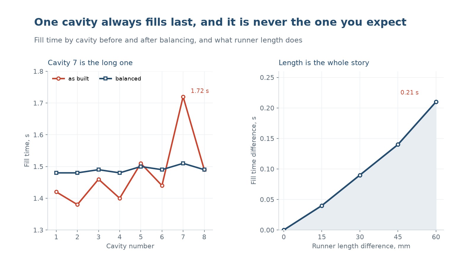
On a measured eight-cavity tool the fill times were 1.42, 1.38, 1.46, 1.40, 1.51, 1.44, 1.72 and 1.49 seconds. The slowest was cavity 7, at 1.72, and cavity 5 was second at 1.51. Both are middle cavities on the far side of the sprue, not corners.
That pattern is common and it is not random. The corner cavities are fed by the longest path, but they are also fed by a branch that has only one cavity downstream, so the flow rate through that branch is high and the shear heating is high. The middle cavities on the far side are fed by a branch that splits twice, and the split leaves each with half the flow, half the shear heating, and a cooler melt.
The result is that the cavity with the longest path is not necessarily the one that fills last. The one that fills last is the one with the worst combination of path length and low shear heating, and on a symmetric layout that is a middle cavity on the far side.
This matters because the usual fix, adding length to the short runners, makes it worse. If cavity 7 is slow because its melt is cold, lengthening the runner to cavity 1 to slow it down does not warm cavity 7; it just moves the problem.
Runner length, shear and the fill-time spread
The direct relationship is simple and it is worth knowing the size of it. On a typical eight-cavity tool running a 2.5 mm diameter runner, a 60 mm difference in runner length is 0.21 seconds of fill time difference. Fifteen millimetres is 0.04 seconds, thirty is 0.09, forty-five is 0.14.
Whether 0.21 seconds matters depends on the process. On a part with a 1.5 second fill, a 0.21 second spread means the last cavity is filling at a pressure the first cavity saw 14 percent earlier, and the last cavity is packing against a melt that has had 0.21 seconds more to cool. On a thin wall that is a short shot; on a thick wall it is a sink mark on one cavity out of eight.
The spread can be reduced by changing the runner, or by changing the process. Raising the melt temperature narrows the spread because the viscosity difference between paths falls; raising the injection rate does the same because shear thinning flattens the resistance difference. Both of them widen the process window rather than fixing the tool, and both of them are worth trying before a tool is re-cut.
Changing the runner means changing the diameters, not the lengths. A short runner with a smaller diameter has a higher pressure drop, which is how a geometrically unbalanced tool is made to fill evenly. The correction is calculated from the pressure drop equation, and it is usually a 0.2 to 0.4 mm diameter change on one or two branches.
| Runner length difference | Fill time difference | Effect on an 8-cavity tool |
|---|---|---|
| 0 mm | 0.00 s | Ideal, rarely achieved |
| 15 mm | 0.04 s | Within a normal window |
| 30 mm | 0.09 s | Visible in part weight |
| 45 mm | 0.14 s | Short shots at the thin end |
| 60 mm | 0.21 s | One cavity needs its own process |
Table 1 — What a runner length difference costs in fill time
What balancing actually changes
Balancing does not make all cavities fill at once. It makes them fill close enough together that one packing pressure suits all of them. On the measured tool, balancing took the spread from 0.34 seconds to 0.03, and the effect on the part was a weight spread that went from 4.8 percent to 0.6 percent.
The weight spread is the number to watch, because it is the one that reaches the customer. Fill time is a process variable; part weight is the result. A tool with a 1 percent weight spread is a tool that will run at a stable process; a tool with a 5 percent spread needs the process set for the worst cavity, which means the other seven are overpacked.
Overpacking is not free. It raises the internal stress in seven cavities to fix one, and it shows up as flash on the overpacked cavities and as a heavier part than the drawing allows. It also raises the clamp force requirement, which can push a tool onto a larger press.
The other thing balancing changes is the cooling. A cavity that fills late is a cavity that starts cooling late, so it is hotter at ejection. On a tight-tolerance part that is a dimensional difference between cavities, and it is often mistaken for a tool dimension error until someone measures the cavity temperature.
Telling a balance problem from something else
A short shot on one cavity out of eight is the classic balance symptom, and it has at least four other possible causes. Before cutting the runner, rule them out.
Venting: a cavity with a blocked vent traps air and cannot fill, and it behaves exactly like a cavity with a long runner. The test is to run the tool at a very low injection rate; a balance problem gets worse, a venting problem gets better because the air has time to escape.
Gate freeze: a cavity with a smaller gate freezes before it packs, so it is light and sinks. The test is to weigh the parts and look at the gate area; a frozen gate leaves a distinct dimple.
Cooling: a cavity with a blocked cooling circuit runs hot, and a hot cavity fills more easily but ejects soft and shrinks more. The test is a thermal image of the tool at ejection.
Only after those three are excluded is it a balance problem, and even then the first fix is the process, not the tool.
| Symptom | Balance | Venting | Gate freeze | Охлаждение |
|---|---|---|---|---|
| Short shot on one cavity | Да | Да | Sometimes | Нет |
| Worse at low injection rate | Да | No, better | Нет | Нет |
| Light part with sink at gate | Нет | Нет | Да | Нет |
| Hot cavity at ejection | Slight | Нет | Нет | Да |
| Weight spread across cavities | Large | Large | Средний | Small |
Table 2 — Separating the four causes of one bad cavity
When to re-cut and when to leave it
A tool that holds a 1 percent weight spread does not need re-cutting, whatever the fill-time plot looks like. A tool that holds 3 percent and needs a process window so narrow that the operator cannot hold it through a shift does.
The decision is economic. Re-cutting a runner is a day of toolroom time plus a re-qualification, and it buys a wider window for the life of the tool. Leaving it costs a slower cycle and a higher scrap rate, every shift, for the same life. On a high-volume part the re-cut pays back in weeks; on a 5,000-part order it never does.
There is a middle route: change the gate, not the runner. A gate is much cheaper to modify than a runner, and a 0.1 mm change in gate diameter moves the fill balance almost as much as a 0.3 mm change in runner diameter. It is the first thing to try when one cavity is consistently out.
Why does a middle cavity fill last instead of a corner?
Because the corner is fed by a branch with high flow and high shear heating, so its melt is hotter. A middle cavity on the far side gets half the flow after the split, less shear heating and a cooler melt, which can outweigh its shorter path.
How much fill time does a runner length difference cause?
About 0.21 seconds for 60 mm on a 2.5 mm runner. Fifteen millimetres is 0.04 seconds, thirty is 0.09, forty-five is 0.14.
What weight spread is acceptable across cavities?
One percent or less runs at a stable process. Three percent needs a narrow window. Five percent means the process is set for the worst cavity and the rest are overpacked.
How do I know it is balance and not venting?
Run the tool at a very low injection rate. A balance problem gets worse because the melt has more time to cool; a venting problem gets better because the air has time to escape.
Is it cheaper to change the gate or the runner?
The gate, by a wide margin. A 0.1 mm gate diameter change moves the balance almost as much as a 0.3 mm runner change, and it is a fraction of the toolroom time.
Can raising the melt temperature fix an unbalanced tool?
It narrows the spread, because a hotter melt has a smaller viscosity difference between paths. It widens the process window rather than fixing the tool, and it is worth trying before any re-cut.
One cavity that will not fill, or a weight spread you cannot hold?
Send the runner layout, the cavity count and the part weight by cavity. We will tell you whether it is balance, venting or cooling, and whether the fix is a gate or a runner.




 RU
 EN
 ES
 FR
 DE
 PT
 AR
 JA
 KO
 IT
 NL
 TR
 PL
 ID
