
The problem
Symptom. An in-line gauge logs thickness only at the head and tail of each coil, so a mid-coil drift that crosses the tolerance is never recorded and the lot ships blind.
What it costs. A customer complaint on a thin mid-coil section forces an illustrative 10 h of investigation and a stop-ship while the logging interval is fixed.
This article quantifies the undetected drift by log interval, sets the logging cadence, and writes the alarm rule into the process plan.
When the log misses the middle of the coil
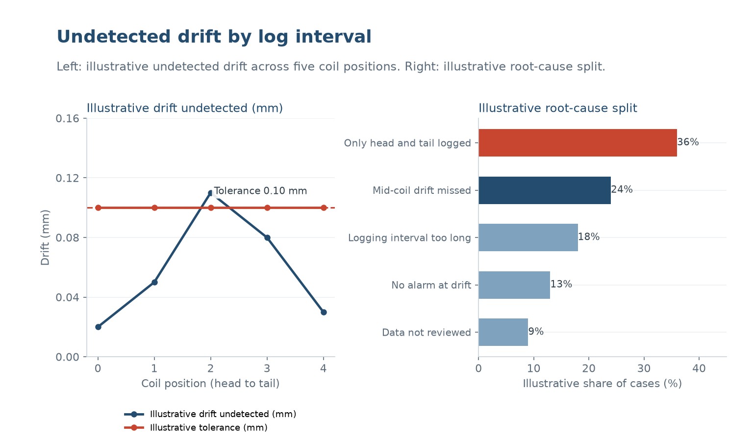
In one illustrative case an in-line gauge records thickness only at the head and tail of each coil, so a mid-coil drift to 0.11 mm against a 0.10 mm tolerance ships unrecorded and the customer finds it first.
| Gap trigger | What it hides | First figure to check |
|---|---|---|
| Head and tail only | Mid-coil drift | Drift vs 0.10 mm |
| Customer finds it | Stop-ship raised | Illustrative 10 h probe |
| No alarm | Drift ships blind | Log interval set |
| Lot recalled | Stock replaced | Daily log review |
Table 1 - Reading a thickness log gap before fixing the interval
Need a fixed price for this profile?
Send the cross-section drawing, material, cut length and annual volume. We will review die, calibration and tolerance, then return a written tooling and production quotation.
Quantify the undetected drift by log interval
Quantify the gap before closing it. Five coil positions return illustrative undetected drifts of 0.02, 0.05, 0.11, 0.08 and 0.03 mm; the mid-coil point crosses the tolerance because nothing is logged there. These are illustrative worked values from stated assumptions, not a measured series or a quoted result.
A five-step diagnostic sequence
- Set the interval.
Choose a logging interval that records the mid-coil, not only the ends. - Log every position.
Capture thickness at each interval along the coil in the process record. - Raise the alarm.
Trigger an alert when any point crosses the 0.10 mm tolerance. - Review the log.
Read the daily trend so a drift is seen before the coil ships. - File the plan.
Record the interval and alarm so the next coil uses the same rule.
The chart below is a typical result from that measurement step. Use it to separate a design limit from a setting that can still be recovered.
Set the in-line logging cadence
Set the cadence at a logging interval that captures the mid-coil. With the interval shortened, the 0.11 mm drift is caught and alarmed; an illustrative 10 h of investigation is the cost of the head-tail-only log. These are illustrative worked values from stated assumptions, not a market survey, a quoted price or a measured series.
| Clause or parameter | Agreed value | What goes wrong outside it |
|---|---|---|
| Logging interval | Captures mid-coil | Drift ships blind |
| Alarm at tolerance | 0.10 mm | No early warning |
| Daily review | Trend read | Drift found late |
| Plan owner | Named per line | Cadence applied loosely |
Table 2 - Logging clauses for the process plan
A controlled logging-sequence change
Run the change in a fixed order: set the interval, log every position, raise the alarm at drift, then review. The table ranks the actions by escape risk so the mid-coil is never unmonitored.
| Control action | What it fixes | Cost or trade-off |
|---|---|---|
| Shorten interval | Mid-coil caught | More log points |
| Alarm at tolerance | Drift flagged | Alarm to manage |
| Review daily | Trend seen | Review hour |
| Re-check on grade | No drift after change | One owner to maintain |
Table 3 - Logging controls ranked by escape risk
Write the alarm rule into the process plan
Put the rule in the process plan: a stated logging interval, an alarm at the 0.10 mm tolerance, and a daily log review. A written rule turns a blind ship into a controlled release.
Need the section checked before tooling?
Send us the section and the installation conditions. We will review wall balance, tolerance and fixing detail, then return a marked-up drawing with a tooling quotation.
What to send us
- Cross-section drawing with wall thicknesses
- Material and colour
- Installation temperature range
- Fixing method and run length
Keep the cadence current between grades
Re-check the cadence at each grade change, record the 10 h actually avoided, and re-forecast the logging needs. A written plan reviewed on dated evidence settles the thickness question at line rather than at the customer.
Before you release this extruded profile
- The process plan logs thickness at a stated interval capturing the mid-coil
- An alarm triggers at the 0.10 mm thickness tolerance
- The daily log is reviewed for drift before shipment
- The logging interval is re-checked at each grade change
- A named owner maintains the cadence between reviews
Write the measurement temperature and the tolerance into the drawing; most disputes are really about how the part was measured.
Why log the middle?
Drift often peaks mid-coil as the tool warms. A head-tail-only log misses it, so the lot ships blind and the customer finds the thin section first.
How much does the gap cost?
Using illustrative assumptions the complaint and stop-ship cost 10 h of investigation. These are worked example values, not a measured series.
What tolerance applies?
A stated 0.10 mm thickness tolerance. In this illustrative case the mid-coil point reads 0.11 mm, over the line.
Can I log less?
Only if the customer agrees a reduced plan. The default is an interval that captures the mid-coil.
Who owns the cadence?
A named line owner re-checks it at grade changes. Without one owner the interval drifts back to head-tail.
Does the plan expire?
It is valid until the grade changes. Re-checking at each change keeps the log evidence current.
Get a profile that holds its dimension
Send us the profile section, the length and the service conditions. We will review die, calibration and tolerance, then quote tooling and production with a defined measurement method.
To get an accurate quote, send:
- Profile cross-section drawing
- Material and colour
- Cut length and annual volume
- Service temperature and exposure
Why buyers work with Uplastech
ISO 9001, ISO 14001 and ISO 45001 certified. Founded in 2016, with injection moulding lines in Shanghai and an extrusion plant in Jiangsu. Moulding machines from 90T to 1100T and a maximum shot weight of 5100 g. Samples and a written quotation are available on request.
Continue reading
- Extrusion dimensional drift
- Extrusion profile tolerance
- Profile calibration and cooling
- PVC profile weathering and colour
- PVC window profile design
Ready to specify? See our plastic profile extrusion services или request a written quotation.









 RU
 EN
 ES
 FR
 DE
 PT
 AR
 JA
 KO
 IT
 NL
 TR
 PL
 ID