
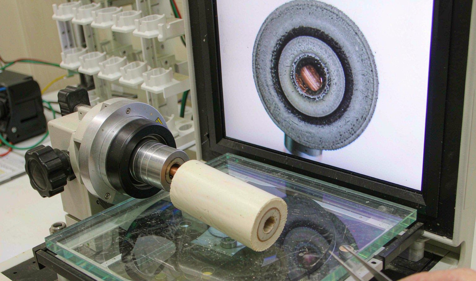
Concentricity is a wall problem
A cable is specified by its overall diameter and by its insulation wall, and of the two the wall is the one that matters. The diameter is what fits in a gland; the wall is what stands between the conductor and everything outside it.
The wall is not uniform, and the variation has two parts. There is a random variation along the length, which is a process capability question, and there is a systematic offset, which is the conductor not being centred in the insulation. The offset is the one that dominates, because it is a bias: it makes one side thin for the whole length of the drum.
The consequence is that the specified wall is a nominal and the real wall is a minimum somewhere. A 1.5 mm nominal wall with 20 percent eccentricity has a 1.2 mm thin side, and the cable is a 1.2 mm cable for every purpose that involves voltage.
Breakdown follows the thin side
Breakdown voltage against minimum wall is close to linear in the range that matters: 8.2 kV at 0.5 mm, 17.1 kV at 1.0 mm, 25.8 kV at 1.5 mm, 34.2 kV at 2.0 mm and 42.5 kV at 2.5 mm.
Linear is the important part. It means a 20 percent loss of wall is a 20 percent loss of breakdown voltage, with no threshold and no safety net. A cable that was designed with a 25 percent margin and then made with 20 percent eccentricity has a 5 percent margin, and 5 percent is inside the tolerance of the test.
The same arithmetic applies to the partial discharge inception voltage, which is the number that actually matters for a medium voltage cable. A void or a thin spot starts discharging at a voltage well below breakdown, and the discharge eats the insulation until the breakdown follows. That is why a cable can pass a breakdown test and fail in service two years later.

What actually moves the conductor off centre
The die centres the conductor, and everybody adjusts the die. That is often not the problem. The single largest cause of a systematic eccentricity on a real line is take-up tension, because a conductor pulled to one side leaves the die to one side and stays there.
The numbers are large. At 20 N of tension the eccentricity is 2.8 percent, at 40 N it is 5.1, at 60 N it is 8.2, at 80 N it is 12.4, and at 100 N it is 17.1 percent. A line running at 100 N of tension cannot be centred by any die adjustment, because the offset is being imposed downstream of the die.
The other causes are thermal and mechanical. The crosshead expands as it heats, and it expands unevenly, so a line that was centred cold is not centred hot. The capstan and the guide rollers wear and drift. And the die itself wears, usually more on one side, which produces a slow drift over months.
The diagnostic order matters. Check the tension and the guides first, then the thermal centring, and adjust the die last. A die adjustment made to compensate for a tension problem is a die adjustment that will have to be undone when the tension is fixed.
How it is measured, and why the method matters
The reference method is a cross-section under a microscope or a profile projector. A slice is cut, mounted, polished and measured at several angular positions, and the result is a set of wall readings from which the minimum, the maximum and the eccentricity are calculated. It is accurate, it is slow, and it is a sample.
The production method is capacitance. A conductor, an insulation and a screen form a capacitor, and the capacitance per unit length depends on the ratio of the diameters. An eccentric core changes the capacitance seen by a set of electrodes around the cable, and the variation as the cable rotates gives the eccentricity directly.
The capacitance method is continuous, non-destructive and it runs at line speed, which makes it the only way to know what the whole drum looks like. It needs a calibration against a section, and it needs the cable to rotate or the electrodes to rotate, which is why it is usually built into the diameter gauge.
X-ray is the third method and it is used for the cases the other two cannot see: a multi-core cable where the cores are not concentric with the sheath, or a cable with a metallic screen that blocks the capacitance measurement. It is a line tool and it costs accordingly.
| Methode | Coverage | Gives | Limit |
|---|---|---|---|
| Section, microscope | Sample | Absolute wall, eccentricity | Langzaam |
| Profile projector | Sample | Wall, ovality | Langzaam |
| Capacitance | 100% | Eccentricity, online | Needs calibration |
| X-ray | 100% | Core positions, sheath | Kosten |
Table 1 — Concentricity measurement methods and what each can and cannot do
What the numbers should be
The limits are set by the standard and by the customer, and they are usually expressed as a minimum wall as a percentage of nominal rather than as an eccentricity. A common requirement is a minimum wall of 90 percent of nominal, which corresponds to about 10 percent eccentricity, and a tighter one is 95 percent.
The tighter limit is expensive and it is worth understanding why. To hold 95 percent minimum wall the process has to hold about 5 percent eccentricity, which means the tension, the guides and the thermal centring all have to be controlled, and the line speed usually has to come down. That is a real cost and it should be attached to a real requirement.
| Requirement | Eccentricity | Minimum wall | Where used |
|---|---|---|---|
| General | 15% | 85% of nominal | LV flexible cord |
| Standard | 10% | 90% of nominal | Building wire, control |
| Tight | 5% | 95% of nominal | MV power, instrumentation |
| Precisie | 3% | 97% of nominal | Coaxial, RF |
Table 2 — Typical concentricity requirements and what they cost
Fixing a drifting line
Start with the tension. Measure it at the take-up and at the capstan, and check that the guide rollers are free and aligned. A roller that has worn a flat will pull the conductor sideways once per revolution, which shows up as a once-per-revolution variation in the capacitance signal and is often misread as a die problem.
Then the thermal centring. Run the line to temperature with a scrap conductor, measure a section, and adjust the die hot. A die centred cold will be off by the differential expansion of the crosshead, which on a large head is several hundredths of a millimetre.
Then the die itself. Check the die bore for wear and for a burr, and check that the die is seated squarely. A die that is not square produces an eccentricity that rotates with the die, which is a useful diagnostic: if the eccentricity follows the die and not the cable, the die is the problem.
Why is concentricity more important than diameter?
Because the insulation fails where it is thinnest. A cable with the correct diameter can have a thin side that halves its breakdown voltage, and the diameter measurement will not show it.
What causes a cable to go eccentric?
Most often take-up tension pulling the conductor to one side, then thermal expansion of the crosshead, then guide and capstan wear, then die wear. Check them in that order.
How is concentricity measured online?
By capacitance. The conductor, insulation and screen form a capacitor, and the variation as the cable rotates gives the eccentricity. It is continuous and non-destructive and it needs a section to calibrate against.
What eccentricity should a medium voltage cable hold?
About 5 percent, which gives a minimum wall of 95 percent of nominal. General purpose low voltage cord is usually allowed 15 percent.
Can a die adjustment fix a tension problem?
No. If the conductor is being pulled to one side after the die, adjusting the die only moves the problem. Fix the tension and then re-centre the die hot.
Why does eccentricity vary once per revolution?
A worn or misaligned guide roller, or a capstan with a flat. The period matches the rotation of the item that is causing it, which is how you identify which one.
A cable that fails on wall or on partial discharge?
Send the construction, the section and the line data. We will tell you whether it is tension, thermal centring or the die, and what the wall should be.
Continue reading
- Wire Insulation Extrusion: Concentricity, Wall and the Spark Tester
- Cable Jacket Extrusion: Pressure Die, Drawdown and Surface Finish
- Crosslinked PE Cable: Silane, Peroxide and the Process Behind Each
- Cable Colour Coding: Stripes, Rings and the Identification Nobody Reads
- Plastic Extrusion Solutions: Profile, Sheet, Pipe and Tube




 NL
 EN
 ES
 FR
 DE
 PT
 AR
 RU
 JA
 KO
 IT
 TR
 PL
 ID
