
What the die has to do
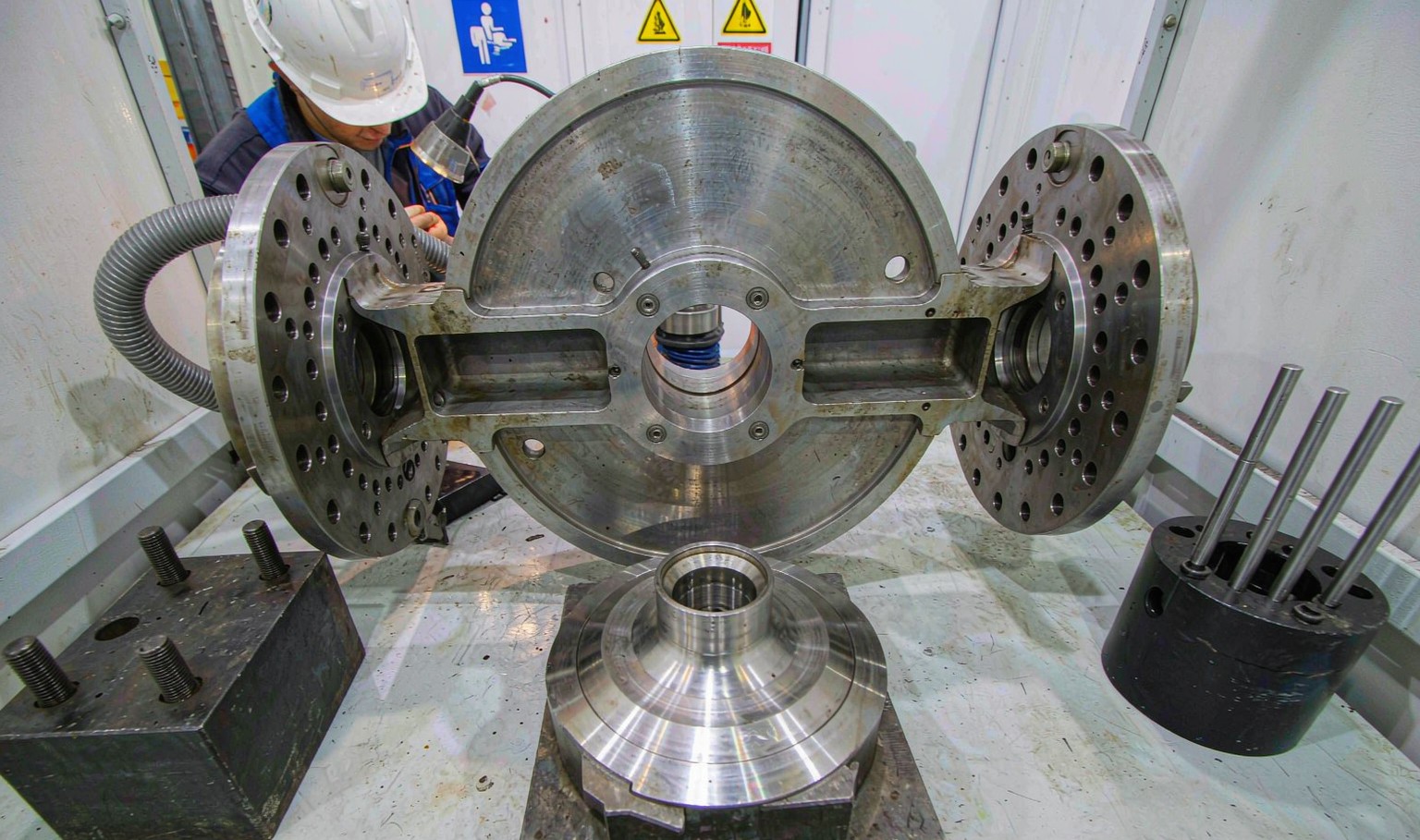
The die takes a cylindrical stream of melt and turns it into a profile with a defined cross section, at a uniform velocity across that section, at a temperature that is still within the material's window. Those three requirements conflict, and every die design is a compromise between them.
Uniform velocity is the hardest. The melt arrives at the die with a velocity profile of its own, and the die has to redistribute it. That is done by making the flow path longer where the material would otherwise move faster, which is the whole principle of a die with a variable land length.
Temperature is the second. The die adds shear heat, and the shear is highest where the flow is fastest. A die that equalises velocity also equalises shear heating, which is why a well designed die runs at a more uniform temperature than a poorly designed one at the same output.
Pressure is the third. The die has to develop enough back pressure to give a stable output without exceeding what the screw can generate. That is a matter of the total flow area and the land length, and it is the part of the design that is easiest to get wrong in the direction of too much restriction.
Land length is the equaliser
The land is the straight, parallel section at the exit of the die. Its job is to remove the memory of the flow path upstream and deliver the melt in a uniform direction. A short land does not have time to do that, and the profile comes out with a velocity distribution inherited from the channel.
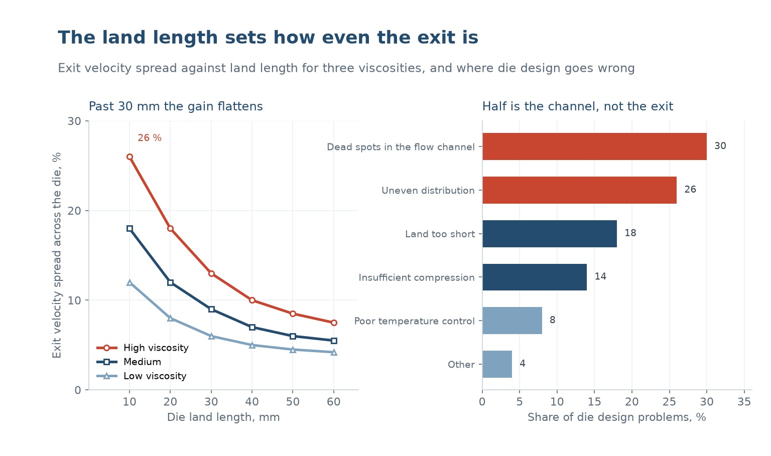
The chart on the left plots exit velocity spread against land length for three viscosities. At 10 mm the spread is 26 percent for a high viscosity melt, 18 for a medium one and 12 for a low one. By 30 mm they are 13, 9 and 6, and beyond 40 mm the curves flatten.
The flattening is the important part. Going from 10 to 30 mm of land cuts the spread by half; going from 30 to 60 cuts it by another third and adds pressure drop and die swell. The practical land length is 20 to 40 mm for most profiles, and the exact number depends on how much pressure the line can afford.
High viscosity materials need more land, which is why a die for rigid PVC is longer than one for the same profile in LDPE. The PVC die also needs a smoother channel and a more gradual taper, because PVC degrades in a dead spot rather than just building up carbon.
The flow channel and its dead spots
The chart on the right puts dead spots at 30 percent of die design problems and uneven distribution at 26. A dead spot is a region where the melt stops moving: a sharp internal corner, a step in the channel, a thread that is not sealed, a thermocouple pocket that protrudes into the flow.
Material in a dead spot sits at temperature for hours. It crosslinks, then carbonises, then breaks off in flakes that appear in the product as black specks. The defect is intermittent and always in the same place on the profile, which is the clue that identifies it.
The design rule is that every surface the melt touches should be either swept by the flow or removable for cleaning. A channel with a radius of at least 3 mm at every internal corner, no steps facing upstream, and no threaded joints in contact with the melt will run for months without shedding.
Uneven distribution is the second problem and it is a design issue rather than a contamination one. A coat hanger manifold, a fishtail, or a simple T are the three common approaches, and each has a range of width to thickness over which it distributes evenly. Running a die outside its design range produces a profile that is thick in the middle and thin at the edges, or the reverse.
Compression inside the die
The die also has a compression ratio of its own: the ratio of the flow area at the inlet to the area at the exit. A die with a high compression ratio accelerates the melt and aligns it, which improves the surface. A die with a low one lets the flow separate and produces a rough or wavy surface.
For most profiles a die compression ratio of 3 to 6 is used, with higher values for materials that need a lot of alignment, such as filled compounds. Too high and the pressure drop becomes the limit on output; too low and the surface quality suffers no matter what the temperature is.
The compression has to happen gradually. A sudden reduction in area creates a dead spot upstream of it and a recirculation zone downstream, and both of them build up material. A taper of 15 to 30 degrees included angle is the usual compromise between length and flow quality.
Diagnosing an uneven profile
Measure the profile at several points across its width, at a steady state. A profile that is thick in the middle and thin at the edges is under-distributed, which means the manifold is too small for the width or the land is too short at the edges. A profile that is thick at one edge only indicates a temperature difference across the die.
Check the die temperature with a contact probe at several points, not with the controller reading. A zone that is 10 C cooler on one side will show as a thickness difference, and the controller will not see it because it is measuring at one point.
Then check the land. A die that has been polished or reworked may have a land that is shorter on one side, and that side will run faster. Measuring the land length around the perimeter with a depth gauge takes ten minutes and settles the question.
| Symptom | Likely cause | Check |
|---|---|---|
| Thick middle, thin edges | Manifold too small | Die width against its design range |
| Thick one edge only | Temperature difference | Contact probe across the die |
| Black specks in one place | Dead spot | Internal corners, thermocouple pocket |
| Rough surface at all temperatures | Low die compression | Inlet to exit area ratio |
| Output limited by pressure | Land too long or die too tight | Land length, flow area |
| Profile curves on cooling | Uneven velocity | Land length at the edges |
Table 1 — Reading the profile to find the die problem
Keeping a die working
A die is a precision part and it is treated as a consumable. The land wears, the chrome wears through, and the flow channel acquires a film of degraded material that is invisible until it flakes. Cleaning it properly, with a brass tool and a controlled burn out rather than a steel scraper, is the difference between a die that lasts ten years and one that lasts three.
The land is the part that wears fastest, because it sees the highest shear and the most abrasion from filled materials. A land that has worn by 0.1 mm has changed the pressure drop and the velocity distribution, and the profile will drift. Checking the land dimensions annually, against the drawing, catches it before the profile goes out of tolerance.
Polishing is not just cosmetic. A rough channel holds material, and held material degrades. A die that is polished every year runs cleaner than one that is only cleaned, and the difference shows up as a lower rate of black specks rather than as a better surface.
| Task | Frequency | Methode | Waarom |
|---|---|---|---|
| Purge and clean the channel | Every material change | Brass tool, controlled burn out | Prevents carbon build up |
| Measure the land | Annually | Depth gauge around the perimeter | Detects wear and rework |
| Polish the flow surfaces | Annually | Diamond paste, felt bob | Reduces hold up |
| Check the heaters and probes | Quarterly | Contact thermometer | Uneven temperature is invisible |
| Inspect for cracks | Annually | Dye penetrant | A cracked die fails suddenly |
Table 2 — A die maintenance schedule that pays for itself
The dye penetrant check is the one that is almost never done and the one that prevents a catastrophic failure. A die that cracks in service dumps a stream of melt onto the line, and the repair is a new die rather than a polish.
How long should a die land be?
Twenty to forty millimetres for most profiles. Ten millimetres does not equalise the velocity; beyond forty the gain is small and the pressure drop keeps rising. High viscosity materials need the longer end of the range.
Why does my profile come out thick in the middle?
The manifold is not distributing evenly across the width, usually because the die is running wider than its design range or the land is shorter at the edges. Check the land length around the perimeter first.
What causes black specks from a die?
A dead spot. Material stops moving in an internal corner, a step or a thermocouple pocket, sits at temperature until it carbonises, then breaks off. The specks always appear in the same place on the profile.
What is die compression ratio?
The ratio of the flow area at the die inlet to the area at the exit. Three to six is typical; higher values align the melt and improve the surface, lower values give a rough surface that no temperature setting will fix.
Can a worn die be reworked?
Yes, up to a point. The land can be re-polished and the flow channel can be re-machined, but each rework changes the pressure drop and the velocity distribution, so the die has to be requalified against the profile tolerance.
How often should a die be polished?
Annually for a die in continuous service, and after any material change that leaves a residue. Polishing is not cosmetic: a rough channel holds material, and held material degrades into the next run.
Profile out of tolerance or shedding specks?
Send the profile drawing, the die drawing and a photograph of the defect. We will tell you whether it is the land, the channel or the temperature.
Continue reading
- Die Swell: Why the Profile Leaves Bigger Than the Die
- Melt Fracture and Sharkskin: Surface Defects With a Rheological Cause
- Screen Changers: Filtering the Melt Without Stopping the Line
- Extrusion Output Rate: What Limits It and What Only Appears To
- Extrusion Screw Design: Compression Ratio, Metering Depth and L/D




 NL
 EN
 ES
 FR
 DE
 PT
 AR
 RU
 JA
 KO
 IT
 TR
 PL
 ID
