

Why the review is worth doing
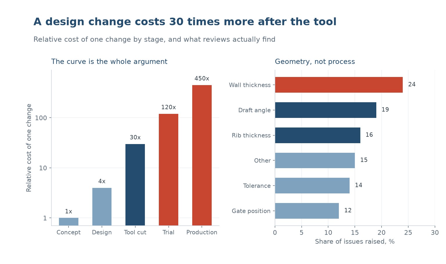
A design change costs roughly one unit of effort at the concept stage, four at the design stage, thirty once the tool is cut, a hundred and twenty at trial and four hundred and fifty in production. The numbers are relative rather than absolute, but the shape of the curve is real and it is the entire argument for a formal review.
The curve is steep because each stage adds something that has to be undone. At concept, a change is an edit. At design, it is an edit plus a drawing revision. At tool cut, it is a tool modification, a re-trial and a delay. In production, it is all of that plus a stock write-off and a customer conversation.
A DFM review is not a design review. A design review asks whether the part works. A DFM review asks whether it can be moulded at the quoted price, in the quoted tool, at the quoted cycle time. Those are different questions and they are often answered by different people.
The review is also the point at which the moulder's experience enters the project. A moulder who has made two hundred similar parts knows which features cause trouble and can say so in ten minutes. That knowledge is free at the quoting stage and expensive to obtain later.
Wall thickness is the first question
Every other decision follows from the wall. A wall that is too thick sinks, warps and takes a long time to cool. A wall that is too thin needs high pressure, may not fill, and is sensitive to material variation. The target is the thinnest wall that carries the load, held as uniform as the design allows.
The practical range depends on the material and the flow length. A small part in ABS can run at 1.2 mm; the same part in a glass-filled nylon needs 1.5 mm to fill reliably. As a rule of thumb, the flow length divided by the wall thickness should stay under 150 for an easy material and under 100 for a difficult one.
The variation within a part matters as much as the absolute value. A wall that goes from 1.5 mm to 4 mm in one step will sink at the thick end and warp along the transition. The rule that keeps this under control is a maximum ratio of about 2:1 between the thickest and thinnest wall, with a gradual transition between them.
Thick sections can usually be cored out rather than tolerated. A 6 mm boss becomes a 1.5 mm wall with a 3 mm hole, which cools faster, uses less material and sinks less. The core is often the single biggest improvement available in a DFM review.
Draft angle and the features that need it
Draft is the taper that lets the part leave the tool. Without it the part drags, scuffs and in the worst case stays in the cavity. The usual minimum is one degree per side on a smooth surface, two degrees on a textured surface, and three degrees on a deep draw.
Textured surfaces need more draft because the texture is a series of small undercuts. A deep texture of 0.1 mm on a wall with one degree of draft is effectively zero draft or negative draft, and the part will scuff every time. The rule most moulders use is one additional degree per 0.025 mm of texture depth.
Draft is the item most often missed in the review and the most expensive to add later, because adding draft to a feature usually means moving the feature, which means moving whatever is attached to it. A part that comes to review with zero draft on four features will need a design change, not a tool modification.
The features that catch people out are the ones that look vertical: a cosmetic side wall, a logo pocket, a shallow recess, a slot for a cable. All of them need draft, and all of them are easy to draw without it because the CAD default is zero.
Ribs, bosses and the metal that is not there
A rib is a thick section disguised as a thin one. A rib that is 60 percent of the wall thickness at its base will sink on the opposite face, because the material there is effectively 1.6 times the wall. The usual guidance is 50 to 60 percent of the wall at the base, tapering to 40 percent at the tip, with a radius at the root.
Bosses are worse because they are round and they sit on a wall. A boss with a 3 mm wall on a 2 mm wall is a 5 mm mass, which sinks on the far side and often cracks at the root when the screw is driven. Coring the boss to a 1.5 mm wall and adding gussets is the standard fix.
The number of ribs matters as much as their size. A grid of ribs on a 2 mm wall creates a series of thick nodes where they cross, and those nodes sink. Spacing the ribs at least two wall thicknesses apart, and avoiding crossing ribs where possible, keeps the sink under control.
The review question is not whether the ribs are strong enough, it is whether the ribs can be moulded. A structural analysis that says a rib is needed at 70 percent of wall thickness is correct and also unmanufacturable, and the answer is more ribs at 50 percent rather than fewer at 70.
Tolerances that can be held
A tolerance is a promise, and a DFM review is where the promise is checked. A moulded part can hold plus or minus 0.05 mm on a small dimension in a single cavity, and about 0.1 percent of the dimension on anything larger. Anything tighter needs a secondary operation or a different process.
The tolerances that cause the most trouble are the ones across a parting line, the ones between features in different tool halves, and the ones on a dimension that spans a weld line. All three are achievable to about plus or minus 0.12 mm and no better, regardless of what the drawing says.
The second problem is a tolerance that conflicts with the material. A glass-filled grade shrinks less but more variably, so its achievable tolerance is wider, not tighter. A semi-crystalline material shrinks more and its tolerance is wider again. The material choice and the tolerance have to be decided together.
The review should end with a tolerance table that the moulder and the designer both sign. That table is what the first article is measured against, and having it agreed before the tool is cut removes the most common source of dispute at first article.
Gate position and the marks it leaves
The gate is where the material enters and it leaves a mark. On a cosmetic part the gate position is a design decision, not a moulding decision, and it has to be made at the review. A gate on a visible face leaves a witness mark that no amount of process tuning removes.
The gate also sets the flow pattern, and the flow pattern sets the weld lines. Two flow fronts meeting on a cosmetic face leave a visible line; the same two fronts meeting behind a rib leave nothing. Moving the gate moves the weld line, and the review is the last chance to do it for free.
Gate size matters for the material. A small gate on a glass-filled material causes high shear and fibre breakage at the gate, which shows as a weak spot and a cosmetic defect. A hot runner with a properly sized drop costs more than a cold runner and removes the gate mark entirely.
| Check | What good looks like | What it costs if missed |
|---|---|---|
| Wall thickness | Within 2:1 across the part | Sink, warp, long cycle |
| Draft | 1 degree smooth, 2 to 3 textured | Scuffing, part sticking |
| Rib thickness | 50 to 60 % of wall at the base | Sink on the opposite face |
| Boss wall | Cored to 1.5 mm with gussets | Sink and root cracking |
| Toleransi | Within the process capability table | First article rejection |
| Gate position | On a hidden face or a removable tab | A permanent witness mark |
| Weld lines | Behind a rib or off the cosmetic face | A visible line that cannot be polished out |
Table 1 — The seven checks that catch most problems
Running the review so it produces decisions
A review that produces a list of concerns is a waste of an afternoon. A review that produces a marked up drawing and a list of agreed changes is worth a week of tool rework. The difference is whether somebody has the authority to say yes.
The most effective format is short and specific: the moulder presents the drawing with the problem features circled, states what will happen and what the fix is, and the designer accepts or rejects each one on the spot. Forty questions in ninety minutes, with the drawing marked as it goes.
The output should be a revised drawing, not meeting minutes. Minutes get filed; a revised drawing gets built. Any item that cannot be resolved in the meeting should be assigned to a named person with a date, and the tool should not be released until it is closed.
| Item | Owner | When |
|---|---|---|
| Wall thickness and rib review | Moulder and designer | Before tool design |
| Draft on every vertical face | Designer | Before tool design |
| Tolerance table agreed | Both | Before tool design |
| Gate position and weld lines | Moulder | Before tool design |
| Mould flow analysis on the final geometry | Moulder | Before tool cut |
| Prototype fit check | Customer | Before tool cut |
Table 2 — A review schedule that closes before the tool is released
The one item that is most often skipped is the prototype fit check, and it is the one that catches the problems no drawing review finds: a rib in the way of a cable, a face that becomes visible once assembled, a screw boss that does not line up with the hole in the mating part. A machined or printed prototype costs a few hundred euro and settles those questions before the tool exists.
How long should a DFM review take?
Ninety minutes for a typical part, with the moulder prepared and the designer present. The preparation is the expensive part: the moulder needs to have looked at the drawing and marked the problem features before the meeting, not during it.
Who should attend?
The tool designer, the moulder's process engineer and the part designer. The customer's assembly engineer is worth having for the fit check. A review without the tool designer present produces recommendations that cannot be implemented.
Is a mould flow analysis part of the review?
It is the next step after the review, not part of it. Flow analysis answers questions the review raises: where the weld lines land, whether the part fills, where it traps air. Running it on the reviewed geometry is much more useful than running it on the original.
What if the customer refuses the changes?
Document the consequence and quote accordingly. A part with a 70 percent rib will produce sink, and the moulder who says so in writing and prices the sorting is in a better position than the one who stays silent and absorbs the rejects.
Can a DFM review be done on a part already in production?
Yes, and it is often worthwhile when a part is being re-tooled or moved to a new supplier. The same checklist applies, and the findings usually explain a defect that has been accepted as normal for years.
How much does a review actually save?
The cost curve is the answer: a change at the tool stage costs about thirty times a change at the design stage. One avoided tool modification pays for a year of reviews, and the reviews that find nothing are the cheap ones.
About to release a tool?
Send the part drawing and the annual volume. We will run the checklist and send back a marked up drawing with the changes that matter before the steel is cut.
Continue reading
- Part Consolidation: Replacing Five Parts With One and Paying for the Tool
- Wall Thickness Design: The Constraint Everything Else Works Around
- Rib Design: Getting Stiffness Without Sink
- Gate Design: Where the Material Enters Decides Everything After
- Tolerance Stack-Up: Predicting Assembly Before the Tool Is Cut




 ID
 EN
 ES
 FR
 DE
 PT
 AR
 RU
 JA
 KO
 IT
 NL
 TR
 PL
