

- 1. What a vacuum forming mold actually has to do
- 2. The five mold materials and when each is correct
- 3. Draft angles: the numbers that work
- 4. Radii, fillets and the corners that tear
- 5. Vacuum holes and vent slots
- 6. Thermal design: hot molds, cold molds and heat soak
- 7. Shrinkage compensation
- 8. Texture, engraving and surface finish
- 9. Undercuts and the parts you cannot form
- 10. Mold life and the cost per part of a mold
- 11. A mold design review checklist
- 12. Frequently asked questions
- 13. Send the drawing and the annual quantity — we will tell you which mold material pays
On this page
- What a vacuum forming mold actually has to do
- The five mold materials and when each is correct
- Draft angles: the numbers that work
- Radii, fillets and the corners that tear
- Vacuum holes and vent slots
- Thermal design: hot molds, cold molds and heat soak
- Shrinkage compensation
- Texture, engraving and surface finish
- Undercuts, undercuts and the parts you cannot form
- Mold life and the cost per part of a mold
- A mold design review checklist
- Frequently asked questions
What a vacuum forming mold actually has to do
A vacuum forming mold does four jobs, and most of the problems in production trace back to one of them being under-designed.
- It defines the shape. That is the obvious one, and it is the only one most buyers think about.
- It lets the air out. The sheet has to be pulled onto the surface. Air trapped between the sheet and the mold has to escape through holes, or the sheet will not touch down.
- It removes heat. In thin-gauge forming the mold is a heat exchanger. A sheet at 160 °C has to be brought to a temperature where it holds shape, and the mold is the only thing available to do it.
- It survives. Not for one part — for the production run, at temperature, with a sheet being dragged across it thousands of times.
Those four requirements pull against each other. A material that conducts heat well (aluminium) is expensive and heavy. A material that is cheap and easy to shape (wood, plaster) insulates, so it runs hot and cycles slowly. A mold with generous draft and large radii forms reliably but may not give you the part geometry you drew.
The one rule that governs everything else: in vacuum forming the mold is the inside of the part. Every dimension on the mold is an internal dimension. Wall thickness is not controlled by the mold at all — it is controlled by how the sheet stretches. That is why mold design and wall thickness are separate disciplines, and why a perfectly made mold can still produce a part with a 0.4 mm corner.
The five mold materials and when each is correct
There is no single correct mold material. There is a correct material for a quantity, a geometry and a tolerance. The table below is the one we use when quoting.
| Mold material | Typical quantity | Lead time | Relative cost | Thermal conductivity | Meilleur pour |
|---|---|---|---|---|---|
| Wood (MDF, plywood, hardwood) | 1 – 50 | 2 – 5 days | 0.3 – 0.5× | Very low | Packaging prototypes, simple covers, proving a shape |
| Plaster / gypsum | 1 – 30 | 3 – 7 days | 0.3 – 0.6× | Very low | Large display pieces, sculpture, short-run signage |
| Epoxy / glass-filled resin | 50 – 1,000 | 5 – 10 days | 0.6 – 1.0× | Faible | Medium runs, textured surfaces, complex tooling |
| 3D printed (filled polymer) | 10 – 200 | 1 – 3 days | 0.4 – 0.8× | Faible | Rapid iteration, small parts, vented prototypes |
| Aluminium (cast or machined) | 1,000 – 100,000+ | 10 – 25 days | 1.0× | Haut | Production, tight tolerance, textured, high cycle count |
Cost is relative to a machined aluminium mold of the same size. Lead times assume a mold under 1 m² with no complex cooling.
Wood
Wood is the cheapest way to find out whether a shape forms at all. MDF is dimensionally stable enough for a simple male mold, machines easily, and takes a sanded and sealed finish that will release from a sheet. The problems are that it insulates (so cycle time is long), it moves with humidity, it wears at the edges where the sheet drags, and the surface grain will telegraph through a thin sheet.
Wood is correct for a packaging prototype, a trade-show sample, or a first article to check fit. It is wrong for anything you intend to run for a month.
Plaster and gypsum
Used almost exclusively for very large, low-quantity, visually-driven parts — point-of-sale displays, theatrical props, architectural features. Plaster can be cast over a pattern and hand-finished to a shape that would be expensive to machine, and it holds fine detail. It is heavy, brittle, and it dusts. It also cannot take vacuum holes reliably, so plaster molds usually rely on a sintered or drilled insert at the deepest point.
Epoxy and glass-filled resin
The workhorse for medium runs and for textured surfaces. A pattern is machined or printed, a silicone or fibreglass jacket is taken, and the production mold is cast in a filled epoxy. The result is a mold that is light, dimensionally stable, takes a moulded-in texture from the pattern, and can be repaired by casting a patch.
Epoxy molds are also the standard route to a multi-cavity tool at low cost, because the second and third cavities are cast from the same pattern rather than machined separately.
The limitation is thermal. Filled epoxy conducts heat at roughly a fifth of the rate of aluminium, so the mold surface climbs toward sheet temperature over a run. A mold that cycles in 40 s when cold may cycle in 55 s after two hours. That is why epoxy tools for thick-gauge work are often fitted with internal cooling channels cast in place, or with an aluminium face plate.
Moules imprimés en 3D
For iteration speed this is now the default in our shop. A filled polymer print — glass-filled or carbon-filled — gives a mold in a day, with vacuum holes printed in the correct locations rather than drilled afterwards, and with conformal cooling channels if the printer allows it.
The limits are temperature and wear. Most filled filaments soften well below the sheet temperature, so a printed mold works for short runs and for small parts where the sheet does not have much thermal mass. A printed mold also has a layered surface that will telegraph into a glossy sheet unless it is sanded and sealed.
Aluminium
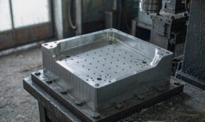
The production answer. Cast aluminium for large, gently-curved molds; machined 6061 or 7075 for smaller, tighter, textured molds. Aluminium conducts heat roughly 200 times better than wood, holds tolerance, takes a bead-blast or a chemical texture, and can be repaired by welding.
The cost is in the block and the machining time. A machined aluminium mold for a part the size of a car door card can cost more than ten epoxy molds, and it only makes sense when the run justifies it.
Common mistake: specifying aluminium for a 200-piece run "because it lasts longer". A machined aluminium mold for a short run costs 2–3× an epoxy tool and saves nothing, because the failure mode in a 200-piece run is not mold wear — it is a design change. Spend the money on a second iteration instead.

Draft angles: the numbers that work
Draft is the taper on every vertical wall that lets the formed part release. Without it the part shrinks onto the mold as it cools and locks. With too little of it, the part releases sometimes — which is worse than never, because it passes inspection and then fails in the field.
The amount of draft you need depends on the surface, the depth and the material.
| Condition | Minimum draft | Comfortable draft |
|---|---|---|
| Smooth mold, shallow draw (< 50 mm) | 1° | 2° |
| Smooth mold, deep draw (> 150 mm) | 2° | 3 – 5° |
| Textured mold (light matte) | 2° + 1° per 0.025 mm texture depth | 3 – 4° |
| Heavy texture / leather grain | 5° | 7 – 10° |
| Male (positive) mold | Add 1° to all the above | — |
| Female (negative) mold, deep cavity | 0.5 – 1° | 1 – 2° |
Draft on a female cavity can be lower than on a male because the sheet shrinks away from the wall rather than onto it. The exception is a deep, narrow female cavity, where the sheet has to be pushed in and the walls must guide it.
Two things about draft that are widely misunderstood:
- Draft is measured from the direction of draw, not from vertical. On a mold with a curved parting line the draft angle on each wall is measured relative to the mold's opening direction. A wall that looks like it has 3° in the CAD model can have 0.5° relative to draw if the parting line is tilted.
- Draft costs height, not width. Adding 2° of draft to a 200 mm deep wall moves the base by 7 mm. That is the number to check against your assembly — not the angle.
The 7 mm rule of thumb: for every 100 mm of draw depth, 2° of draft moves the wall by 3.5 mm. On a deep part, draft is often the constraint that decides whether the part fits, not the wall thickness.
Radii, fillets and the corners that tear
In vacuum forming, a sharp internal corner is a stress concentrator et a thinning point. The sheet has to stretch around the corner, and it stretches from the material immediately adjacent — so the corner ends up thinner than the wall, and the sharper the corner the worse it gets.
| Corner radius (as % of draw depth) | Corner thickness vs nominal wall | Forming reliability |
|---|---|---|
| < 3 % | 35 – 50 % | Poor — tearing and pinholes common |
| 3 – 6 % | 50 – 65 % | Marginal — needs plug assist |
| 6 – 12 % | 65 – 80 % | Bon |
| > 12 % | 80 – 92 % | Excellent |
Corner thickness measured on a 2 mm HIPS sheet at 120 mm draw depth. The relationship is not linear — most of the loss happens in the first 6 %.
Practical rules:
- Minimum inside radius = sheet thickness. This is the floor. Below one thickness the corner will thin and, in a pressure-formed or plug-assisted process, will often pinhole.
- Preferred inside radius = 1.5 × sheet thickness, or 6 % of draw depth, whichever is larger.
- Outside corners should be at least 2 × sheet thickness. A sharp outside corner on a female mold produces a knife edge where the sheet wraps, and that edge is the first thing to crack in service.
- Fillets on ribs and bosses should be at least 0.5 × the rib width. A rib 8 mm wide needs a 4 mm root fillet, otherwise the sheet bridges the root instead of filling it.
Where a design genuinely needs a sharp corner — a machined-looking edge on a display bezel, for example — the usual answer is to form with a generous radius and then machine or trim to the sharp edge. That is a secondary operation with a real cost, and it should be in the quote from the start rather than discovered at first article.
Vacuum holes and vent slots
Vacuum holes are where most first-article failures originate. They are also the cheapest thing on the mold to get right, and the most expensive to get wrong, because a badly placed hole leaves a visible dimple in the part forever.
Size
The hole must pass air fast enough to pull the sheet down before the sheet cools, and be small enough that the sheet does not dimple into it. Both constraints depend on sheet thickness and on how soft the sheet is at the moment it touches down.
| Sheet thickness | Hole diameter | Slot width |
|---|---|---|
| 0.3 – 0.8 mm (thin gauge) | 0.4 – 0.6 mm | 0.3 – 0.5 mm |
| 0.8 – 2.0 mm | 0.6 – 1.0 mm | 0.5 – 0.8 mm |
| 2.0 – 4.0 mm | 1.0 – 1.5 mm | 0.8 – 1.2 mm |
| 4.0 – 8.0 mm (heavy gauge) | 1.5 – 2.5 mm | 1.2 – 2.0 mm |
| > 8 mm | 2.5 – 3.5 mm | 2.0 – 3.0 mm |
Rule of thumb: hole diameter should not exceed about one third of the sheet thickness at the point where the sheet lands. Above that, the sheet pulls into the hole and leaves a dimple that is visible on the outside of the part.
Position and spacing
The instinct is to distribute holes evenly. That is wrong. Holes should be concentrated where the sheet lands last — the deepest point of a female cavity, the top of a male mold, the inside of a tight corner, the far end of a long draw. Those are the places where air is trapped longest, and where the sheet has the least time left to conform.
- Deepest points first. Every local minimum in a female mold and every local maximum on a male mold needs a hole at the centre.
- Corners second. Each inside corner of a female cavity gets a hole within 10 mm of the corner, or a slot along the corner.
- Then a grid. Elsewhere, a grid at 25 – 50 mm pitch for thin gauge, 50 – 100 mm for heavy gauge, is enough to evacuate the volume.
- Never at a visible cosmetic surface. If the outside of the part is the show face and it sits against the mold, a dimple will show. Move the hole to a non-cosmetic area or use a slot in a trim zone.
Vent slots beat round holes on heavy gauge. A slot 1.5 mm × 20 mm passes far more air than a 2 mm hole, and because the sheet bridges a narrow slot rather than being sucked into a round hole, it leaves a much shallower witness mark. On thick-gauge molds we cut slots along the parting line and along every internal corner.
Manifold and evacuation rate
Holes are only half the system. Behind them there has to be a path to the vacuum source with enough cross-section that the pressure at the farthest hole is close to the pressure at the pump. A common failure is a beautifully drilled mold with a 6 mm internal channel feeding 200 holes — the near holes see full vacuum, the far holes see almost none, and the part forms on one side only.
Design the internal manifold at 1.5–2× the total hole area, and give each large mold section its own connection to the vacuum tank rather than daisy-chaining them.
Thermal design: hot molds, cold molds and heat soak
Thin-gauge and thick-gauge forming have opposite thermal requirements, and a mold designed for one will perform badly on the other.
Thin gauge: the mold is a heat exchanger
In thin-gauge (roll-fed, in-line) forming, cycle time is typically 3 – 10 s and the sheet is 0.3 – 1.5 mm. The mold must remove heat fast enough that the part is rigid at ejection. Aluminium with drilled or cast cooling channels is the norm, and mold temperature is actively controlled — usually 20 – 40 °C for PS, PVC and PET, higher for PP and HDPE.
Cooling channel design matters more than mold material here. Channels should follow the part surface at a consistent depth (typically 25 – 40 mm below the surface) rather than being drilled in straight lines that wander close and far. A channel that runs 15 mm below the surface in one area and 60 mm in another produces a part that is rigid in one place and warped in another.
Thick gauge: the mold is a heat store
In heavy-gauge forming, the sheet is 2 – 12 mm and the cycle is measured in minutes. The mold is usually run hot — 60 – 90 °C, sometimes higher — because a cold mold chills the sheet surface instantly and produces chill marks, internal stress and a part that warps as it relaxes.
Hot molds on heavy gauge are usually achieved by circulating water or oil through the mold, or by building the mold from a material that holds heat. The consequence is that the mold is a heat store: it takes 30 – 90 minutes to reach equilibrium, and every part formed during that warm-up is different from the part formed after it. First-article approval has to be done on a warm mold, not a cold one.
| Paramètres | Thin gauge | Heavy gauge |
|---|---|---|
| Sheet thickness | 0.3 – 1.5 mm | 2 – 12 mm |
| Typical cycle | 3 – 10 s | 2 – 20 min |
| Température du moule | 20 – 40 °C (controlled) | 60 – 90 °C (heated) |
| Mold material | Aluminium, always | Aluminium, epoxy, wood for short runs |
| Cooling requirement | Critical — sets cycle time | Moderate — mostly to avoid chill marks |
| Warm-up before first good part | 5 – 10 min | 30 – 90 min |
| Dominant failure mode | Incomplete form, webbing | Warpage, chill marks, uneven thickness |
The two processes share a name and almost nothing else. A mold built for one will not run the other.
Shrinkage compensation
A formed part is smaller than the mold it came off, because the sheet shrinks as it cools. The mold has to be made larger by the shrinkage allowance, and the allowance depends on the material, the draw ratio and the amount of orientation left in the sheet.
| Matériau | Typical shrinkage | Notes |
|---|---|---|
| PS (oriented, OPS) | 0.3 – 0.6 % | Low — sheet is already oriented |
| HIPS | 0.4 – 0.7 % | Consistent, easy to compensate |
| ABS | 0.4 – 0.8 % | Higher in the draw direction |
| PVC (rigid) | 0.3 – 0.6 % | Very consistent |
| PET / PETG | 0.2 – 0.5 % | Depends heavily on whether it is pre-dried |
| PP | 1.2 – 2.0 % | High and anisotropic — plan for it |
| PEHD | 1.5 – 3.0 % | Highest of the common sheet materials |
| PC | 0.5 – 0.7 % | Needs drying, or shrinkage rises sharply |
| PMMA (acrylic) | 0.3 – 0.6 % | — |
Values are for free shrinkage after forming. Constrained features — a part held flat by a frame or a jig while it cools — shrink less in the constrained direction.
Two practical points:
- Shrinkage is not uniform. A drawn wall shrinks differently in the draw direction than across it, because the sheet was stretched in the draw direction and that stretch is partly recovered on cooling. On a deep part the length can shrink more than the width. Compensating with a single percentage is an approximation, and it is usually good enough — but on a deep PP part it is not, and the mold should be cut with the draw direction allowance applied separately.
- Form the first article, measure it, then cut the mold. For anything where the tolerance matters, the sequence is: build the mold slightly oversize, form 10 parts, let them condition for 24 hours, measure, and then machine the mold to final. It costs one extra setup and saves the argument at first article.
Texture, engraving and surface finish
Texture on a vacuum formed part comes from the mold, but it does not reproduce faithfully. The sheet stretches as it forms, so any texture on the mold is stretched with it — more in the draw direction, less elsewhere. A texture that is uniform on the mold becomes a gradient on the part.
| Mold finish | Reproduction on formed part | Draft penalty |
|---|---|---|
| Polished | Gloss, telegraphs every mold defect | None — lowest draft acceptable |
| Bead blast (fine) | Uniform matte, hides minor marks | +0.5° |
| Bead blast (coarse) | Visible grain, stretched in draw areas | +1° |
| Chemical etch (light) | Good, predictable stretch | +1 – 2° |
| Chemical etch (heavy leather grain) | Reduced depth in stretched areas | +4 – 6° |
| Machined (visible tool marks) | Tool marks read as a texture | +1° |
Heavy textures are usually specified on the non-cosmetic face or on parts where the draw is shallow, precisely because deep draw flattens the grain.
Where a heavy texture is essential on a deep part, the usual solution is to texture only the shallow areas and leave the deep draws smooth, or to accept a "texture fade" and specify it in the drawing so that the buyer and the molder agree on what the part will look like.
Engraving — logos, part numbers, date stamps — is cut into the mold as a raised feature, so it appears as a recess in the part. Minimum legible feature on a formed part is roughly 0.3 mm depth and 0.4 mm line width, and the engraving must be on a surface that does not stretch much. A logo placed on a deep draw will be distorted and possibly illegible.
Undercuts and the parts you cannot form
Vacuum forming has one draw direction and no side action. Anything that would prevent the part coming off the mold in that direction is an undercut, and an undercut needs either a design change or a secondary operation.
The routes available:
- Redesign to eliminate it. The cheapest answer and the one to try first. A snap-fit lip that would be an undercut can often become a separate clipped-on part.
- Flexible mold inserts. A silicone or elastomer insert that deforms to release the undercut. Works for small undercuts on short runs; the insert wears and has to be replaced.
- Collapsible or split molds. Two or more mold sections that separate before the part is stripped. Doubles or triples the mold cost and adds a seam line on the part.
- Form it oversize, then cut it. Form a plain wall and machine the undercut afterwards. Accurate, but it is a machining operation and it costs what machining costs.
- Form in two halves and join them. Common on large enclosures and on twin-sheet parts.
The trap: a 0.5 mm undercut looks trivial in CAD and is a mold cost multiplier in production. If a design has an undercut, the question to ask early is not "can you form it" — it is "what does forming it cost, compared with changing the design".
Mold life and the cost per part of a mold
Mold life is not a fixed number — it is a function of material, sheet, temperature and care. The table below is what we plan to, and it is deliberately conservative.
| Mold material | Expected life (thin gauge) | Expected life (heavy gauge) | Dominant wear mode |
|---|---|---|---|
| MDF / plywood | 20 – 100 | 10 – 50 | Edge crush, surface erosion |
| Plaster | — | 10 – 30 | Chipping, dusting |
| 3D printed (filled) | 100 – 1,000 | 50 – 300 | Layer delamination, heat softening |
| Cast epoxy | 1,000 – 10,000 | 500 – 3,000 | Surface wear, corner rounding |
| Cast aluminium | 50,000 – 500,000 | 10,000 – 100,000 | Porosity, hole wear |
| Machined aluminium | 100,000 – 1,000,000+ | 50,000 – 500,000 | Hole wear, texture loss |
Heavy gauge life is lower because the sheet is thicker, hotter and stiffer, so it drags harder across the mold and carries more heat.
Converting that into a cost per part is the calculation that decides the mold material:
Mold cost per part = (Mold cost + (Mold cost × Replacement factor)) ÷ Quantity
Where the replacement factor is how many times the mold has to be replaced or rebuilt over the run. A $3,000 epoxy mold that lasts 2,000 shots, used for 8,000 parts, is 4 molds = $12,000 = $1.50 per part. A $12,000 aluminium mold for the same 8,000 parts is $1.50 per part too — with better tolerance and shorter cycles. The aluminium only becomes clearly cheaper above roughly 20,000 parts.
A mold design review checklist
The list we run before a mold is released to machining. Most first-article problems are on it.
| # | Check | Failure if missed |
|---|---|---|
| 1 | Every vertical wall has ≥ 2° draft measured from draw direction | Part sticks, or releases intermittently |
| 2 | All internal radii ≥ 1 × sheet thickness | Corner thinning, tearing |
| 3 | All external corners ≥ 2 × sheet thickness | Knife edge, cracking in service |
| 4 | Vacuum hole at every local minimum / maximum | Air trap, incomplete form |
| 5 | Hole diameter ≤ ⅓ sheet thickness at touchdown point | Dimples on the show face |
| 6 | Internal manifold ≥ 1.5× total hole area | Weak vacuum at far holes |
| 7 | Shrinkage allowance applied, draw direction separately | Part out of tolerance on length |
| 8 | Texture draft allowance added (1° per 0.025 mm) | Scuffing, glossy streaks on texture |
| 9 | No undercut without a stated release strategy | Mold cannot be stripped |
| 10 | Engraving on a low-stretch area, ≥ 0.3 mm deep | Illegible logo |
| 11 | Cooling channels at consistent depth from surface | Uneven cooling, warpage |
| 12 | Trim line defined and reachable by the trimming method | Trim fixture cost discovered late |
| 13 | Mold fits the machine's platen and clamp height | Cannot run on the intended press |
| 14 | Lifting points and handling for a mold over 40 kg | Shop-floor injury risk |
Items 1 – 6 account for the majority of first-article rejections. Items 11 – 14 account for most of the production complaints that are not about the part itself.
Frequently asked questions
How much does a vacuum forming mold cost?
As a rough guide, a simple mold under 500 mm across is $300 – 1,500 in wood, epoxy or printed polymer, and $1,500 – 6,000 in machined aluminium. A large heavy-gauge mold for a part over 1 m can run $8,000 – 40,000 in aluminium. The variables that move the number most are size, material, whether the surface is textured, and whether cooling is built in.
What draft angle do I need for vacuum forming?
Minimum 1° on a smooth, shallow mold and 2° on anything deeper than 150 mm. Textured molds need 2° plus about 1° for every 0.025 mm of texture depth, so a heavy leather grain typically needs 5 – 7°. Male molds need about 1° more than female molds for the same part.
Can I use a 3D printed mold for production?
For short runs, yes — 100 to 1,000 parts depending on material and sheet thickness. Filled filaments (glass or carbon) hold up far better than plain PLA or PETG. The two failure modes are heat softening when the sheet is thick and hot, and surface wear that gradually rounds the corners and loses detail.
How many vacuum holes does a mold need?
Enough to evacuate the trapped volume before the sheet cools, placed where the sheet lands last. In practice that means one hole at every local minimum, one within 10 mm of every internal corner, and a grid at 25 – 50 mm pitch elsewhere for thin gauge, 50 – 100 mm for heavy gauge. The number matters less than the placement.
Why does my part have dimples on the outside?
The vacuum holes are too large relative to the sheet thickness at the point where the sheet lands, or the sheet is too hot when it touches down. Reduce the hole diameter to under a third of the local sheet thickness, or switch from round holes to narrow slots, which the sheet bridges rather than being drawn into.
Should the mold be male or female?
Female (negative) molds give a better outside surface and tighter external dimensions, because the sheet is pulled against the mold on the show face. Male (positive) molds are cheaper, easier to make and give better thickness distribution on deep draws, but the outside surface is the free face and is less controlled. Most cosmetic enclosures use female molds; most deep technical parts use male molds with plug assist.
How much shrinkage should I allow?
Between 0.3 % and 0.7 % for PS, HIPS, ABS, PVC, PET and acrylic, and 1.2 – 3.0 % for PP and HDPE. Apply it as a scale factor on the mold, and for deep draws on polyolefins apply a separate, larger allowance in the draw direction.
Can a vacuum forming mold be repaired?
Aluminium can be welded and re-machined, and small damaged areas can be built up with metal-filled epoxy. Cast epoxy molds can be patched with the same resin and re-finished. Wood and plaster are effectively consumable. The one repair that is rarely economic is restoring a worn texture, which usually means re-texturing the whole mold or replacing it.
What is the largest part that can be vacuum formed?
Limited by the machine, not the process. Production machines go to roughly 3 m × 2 m for heavy gauge, and larger custom machines exist. Above about 1.5 m the practical constraints become sheet sag during heating, oven uniformity, and the trim tooling rather than the mold itself.
Does mold temperature matter on a short run?
Yes, more than most people expect. A cold mold produces chill marks on the first parts and a part with higher internal stress, which shows up as warpage a day later. Even on a 20-piece run, pre-heating the mold to 60 – 70 °C for heavy gauge will change the parts you get.
Send the drawing and the annual quantity — we will tell you which mold material pays
We quote the mold in two materials side by side, with the cost per part at your volume, so the decision is made on numbers rather than habit. STEP, IGES or a dimensioned drawing is enough to start.






 FR
 EN
 ES
 DE
 PT
 AR
 RU
 JA
 KO
 IT
 NL
 TR
 PL
 ID
