
- 1. 1. Why design rules exist at all
- 2. 2. Wall thickness: the number everything else depends on
- 3. 3. Draft angle: the cheapest line on the drawing
- 4. 4. Radii: where stress and flow both live
- 5. 5. Ribs: stiffness without sink
- 6. 6. Bosses: the most common source of sink marks
- 7. 7. Undercuts, side actions and the cost they add
- 8. 8. Gate position and what it does to the part
- 9. 9. Tolerances and datum strategy
- 10. 10. Snap fits, living hinges and assembly features
- 11. 11. Cosmetic surfaces and texture
- 12. 12. What a real DFM review looks like
- 13. 13. Frequently asked questions
- 14. Send us the STEP file — get a DFM review before you cut steel
On this page
- Why design rules exist at all
- Wall thickness: the number everything else depends on
- Draft angle: the cheapest line on the drawing
- Radii: where stress and flow both live
- Ribs: stiffness without sink
- Bosses: the most common source of sink marks
- Undercuts, side actions and the cost they add
- Gate position and what it does to the part
- Tolerances and datum strategy
- Snap fits, living hinges and assembly features
- Cosmetic surfaces and texture
- What a real DFM review looks like
- Frequently asked questions
1. Why design rules exist at all
Most injection moulding design guidelines get presented as a list of numbers to memorise — 2 mm wall, 1° draft, 60 % rib thickness. That is the wrong way to use them. Every rule is a consequence of one of four physical events that happen to your part inside the tool, and once you understand which event a rule protects against, you can break it deliberately instead of accidentally.
The four events:
- Filling. Polymer melt has to travel from the gate to the furthest point of the cavity before it freezes. If the flow path is too long relative to wall thickness, the part short-shots — no amount of pressure fixes a frozen flow front.
- Packing. After the cavity fills, more melt is pushed in to compensate for shrinkage. Thick sections pack differently from thin ones, and the boundary between them is where sink marks and internal voids appear.
- Cooling. The part has to be rigid enough to survive ejection. Uneven cooling means uneven shrinkage, which means warpage.
- Ejection. The part has to slide off the core without dragging, scuffing or cracking. This is the only thing draft angle does.
Everything below maps back to one of these. A wall thickness rule is a filling and cooling rule. A draft angle rule is an ejection rule. A rib rule is a packing rule. When someone tells you a design "cannot be moulded", they usually mean one of these four events fails, and it is worth asking which.
The economic argument for following them. A design change that costs an hour at the CAD stage costs a day at the tooling stage and a week once the tool is cut. Every undercut you remove before the tool is ordered is money you do not spend on a side action, and every sink mark you design out is a moulding trial you do not run.
2. Wall thickness: the number everything else depends on
Wall thickness sets the flow length the melt has to cover, the cooling time, the clamp force, the part weight and the piece price. It is the single most consequential dimension on the drawing, and it is usually chosen for structural reasons without anyone checking what it does to the process.
Nominal wall by material
| Material | Typical wall | Practical range | Flow length ratio (L/t) |
|---|---|---|---|
| ABS | 2.0 mm | 1.2 – 3.5 mm | 110 – 160 |
| PP (homopolymer) | 1.8 mm | 0.8 – 3.5 mm | 150 – 250 |
| HDPE | 2.0 mm | 1.0 – 4.0 mm | 140 – 220 |
| PS / HIPS | 1.8 mm | 0.8 – 3.0 mm | 130 – 200 |
| PC | 2.5 mm | 1.8 – 4.0 mm | 80 – 120 |
| PA6 / PA66 (dry) | 1.8 mm | 1.0 – 3.0 mm | 120 – 180 |
| POM | 2.0 mm | 1.2 – 3.0 mm | 100 – 150 |
| PBT | 1.6 mm | 1.0 – 3.0 mm | 110 – 160 |
| PMMA | 2.5 mm | 1.5 – 4.0 mm | 90 – 130 |
| PC/ABS | 2.2 mm | 1.5 – 3.5 mm | 100 – 140 |
| Glass-filled PA66 (30 %) | 2.0 mm | 1.2 – 3.0 mm | 70 – 110 |
Flow length ratio is the longest melt path from gate to last-filled point divided by wall thickness. Exceeding it is the most common reason a part will not fill at any pressure.
The L/t figures are the ones that catch people out. A 1 mm wall in PC gives you a flow path of roughly 100 mm — a part the size of a business card. The same wall in PP gives you 200 mm. This is why thin-wall packaging is polypropylene and thin-wall optical parts are not polycarbonate.
Uniform wall, and where it is allowed to break
The default rule is uniform wall throughout the part. The reason is packing: thin sections freeze first and stop transmitting pressure, so a thick section downstream of a thin one never gets packed and will sink. A thick section upstream of a thin one gets packed, then keeps shrinking after the gate freezes, producing a void in the middle.
Where a part genuinely needs different thicknesses, the transition should be gradual — a taper over at least three times the thickness difference, not a step. A step creates a stress concentration, a flow front that hesitates, and a cooling boundary that shows as a shadow on the cosmetic surface.
| Transition | Verdict | Por qué |
|---|---|---|
| 2.0 mm to 2.0 mm | Ideal | Uniform packing, uniform shrinkage |
| 2.0 mm to 2.4 mm over 1.2 mm | Acceptable | Taper of 3× the step, no visible shadow |
| 2.0 mm to 2.4 mm as a step | Marginal | Flow hesitation, stress riser at the corner |
| 2.0 mm to 4.0 mm | Pobre | Thick region will sink or void regardless of process |
| 4.0 mm solid section | Redesign | Core it out, or split into ribs |
A section thicker than about 4 mm in an unfilled resin will almost always show internal voids, because the outside freezes before the centre finishes shrinking.
Solid sections are worth calling out separately. A 6 mm solid boss or a 5 mm solid rib intersection is not just wasteful — it is a guaranteed void or sink. The fix is almost always to core it: replace the solid block with a box section, or with ribs that keep the wall at nominal thickness.
3. Draft angle: the cheapest line on the drawing
Draft is the taper applied to every surface parallel to the direction of mould opening, so the part releases cleanly instead of dragging on the steel. It costs nothing to add in CAD and it is the most frequently omitted feature in designs that arrive from industrial designers.
| Surface | Minimum draft | Recommended |
|---|---|---|
| Unfinished vertical wall, shallow (under 25 mm deep) | 0.5° | 1° |
| Unfinished wall, deep (over 50 mm) | 1° | 1.5 – 2° |
| Polished cosmetic surface | 1° | 2° |
| Textured surface (SPI B grade) | 1.5° + 1° per 0.025 mm texture | 3° |
| Textured surface (SPI C/D, heavy grain) | 3° + 1° per 0.025 mm texture | 5° |
| Core-side wall (shrinks onto core) | 1.5 × cavity-side value | 2 – 3° |
| Deep rib or boss | 0.5° | 1° |
| Ejector-pin boss | 1° | 1.5° |
The core side needs more draft than the cavity side because the part shrinks onto the core as it cools, increasing the normal force against the steel.
The texture rule is the one that costs money. A heavy grain etched 0.1 mm deep needs about 4° of extra draft on top of the base 1.5°, because every peak of the texture acts as a small undercut against the part. Design a 0.5° wall and then specify a heavy texture, and the tool either drags the surface or the moulder has to run the part hotter and slower to compensate — which costs cycle time on every shot for the life of the tool.
Draft also interacts with depth. A 2 mm deep feature with 0.5° of draft tapers by only 0.017 mm — effectively nothing, and the steel will scuff. A 60 mm deep wall with the same 0.5° tapers by 0.52 mm, which is enough. This is why deep draws need more angle, not less.
4. Radii: where stress and flow both live
Sharp internal corners are the most common structural defect in moulded parts, and they are invisible on a rendering. A sharp inside corner is a stress concentration: under load, stress at the corner can be several times the nominal stress in the wall, and moulded-in shrinkage stress adds to it.
- Internal corner radius: at least 0.5 × wall thickness; 0.25 × wall is the absolute minimum. Below that, expect cracking under impact or during ejection.
- External corner radius: internal radius plus wall thickness. This keeps the wall section uniform through the corner — if the outside radius is smaller, the corner becomes a thick section and sinks.
- Fillet at the base of a rib or boss: 0.25 – 0.5 × wall. This is the single most effective change for impact strength in a ribbed part.
Worked example. A 2 mm ABS wall with a sharp inside corner has a stress concentration factor around 2.5. Adding a 1 mm internal radius (0.5 × wall) with a 3 mm external radius drops it to roughly 1.3. Same part, same material, nearly double the impact resistance, zero cost.
Radii matter for flow as well as strength. A sharp corner forces the melt front to change direction abruptly, which is where hesitation, jetting and weld lines start. Generous radii let the front turn smoothly and keep the flow continuous.
5. Ribs: stiffness without sink
Ribs add bending stiffness far more efficiently than thickening the wall. Stiffness scales with the cube of section depth, so a 2 mm wall with 6 mm deep ribs is dramatically stiffer than a 4 mm flat wall, at a fraction of the weight and cooling time. The catch is that every rib is a local thickening, and every local thickening wants to sink on the opposite face.
| Parámetro | Rule | Effect if exceeded |
|---|---|---|
| Rib thickness | 50 – 60 % of nominal wall | Sink mark on the opposite face |
| Rib height | ≤ 3 × wall thickness | Draft and ejection problems, flow hesitation |
| Rib spacing | ≥ 2 × wall thickness between ribs | Cooling between ribs becomes uneven, warpage |
| Rib draft | 0.5° minimum, 1° preferred | Scuffing and ejection drag |
| Rib base fillet | 0.25 – 0.5 × wall | Stress concentration, cracking at the root |
| Rib end | Stop short of the wall by ≥ 1 × wall | Thick corner, sink at the junction |
The 50–60 % thickness rule is a packing rule: a rib at 60 % of wall thickness freezes at roughly the same time as the wall, so both shrink together and neither pulls a sink.
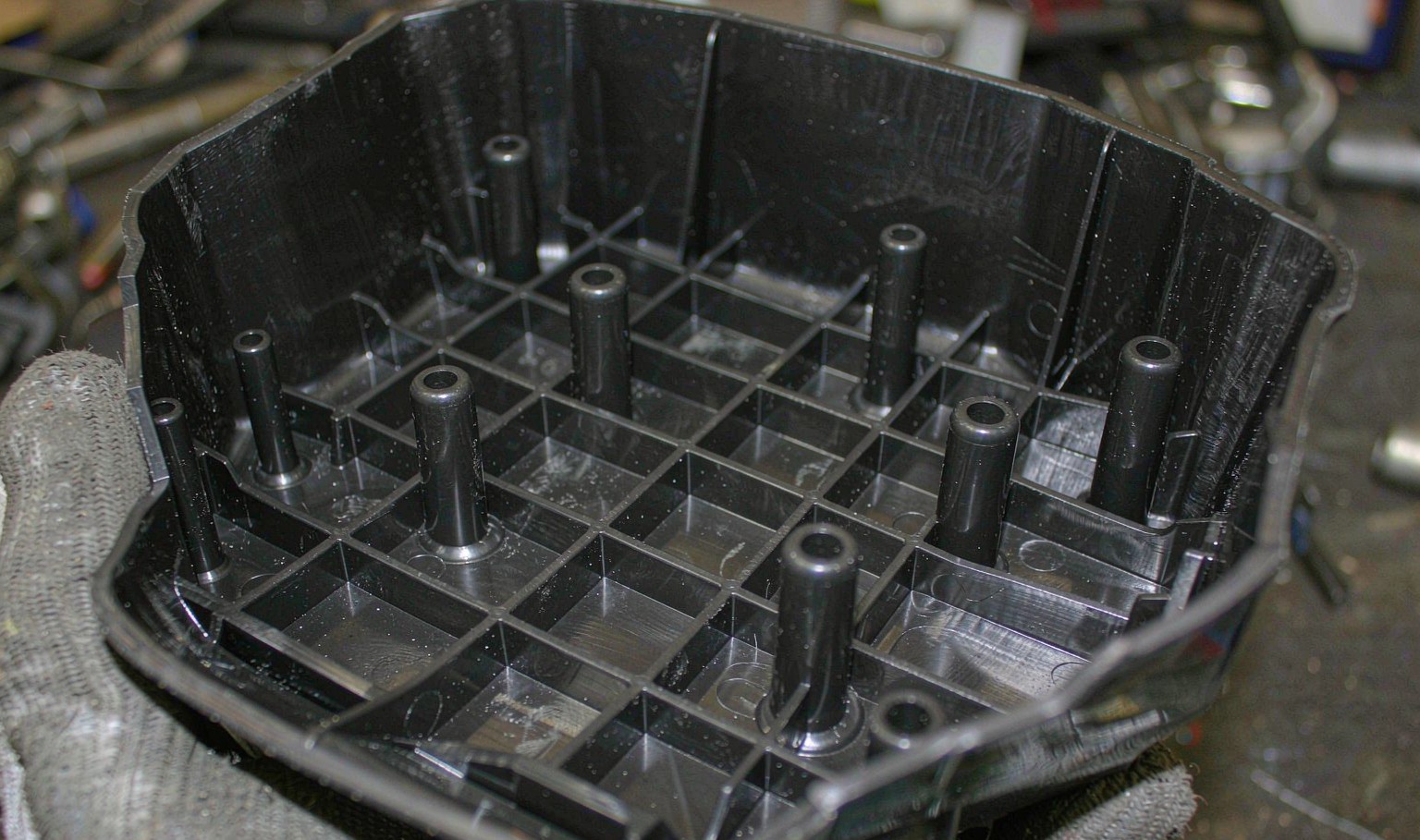
Ribs also have to be treated as flow channels. Melt preferentially races along a rib because the section is thicker, so the cavity fills along the ribs first and the flat panels fill last. That is usually fine, but it can trap air at the far end of a panel or push a weld line into a cosmetic area. If the part has a visible surface, gate and rib layout need to be considered together.
6. Bosses: the most common source of sink marks
A boss is a cylindrical feature, usually for a screw or a press-fit insert. In cross-section it is a ring of material much thicker than the surrounding wall, and it is the single most common cause of a sink mark on the reverse face of a moulded part.
The standard fix is a boss wall at 60 % of nominal wall thickness, with the boss connected to the surrounding wall by ribs or a gusset rather than by a solid web. That keeps every section close to nominal, so everything freezes and shrinks at the same rate.
- Boss outside diameter: typically 2 – 2.5 × the screw or insert diameter, with a wall of 60 % of nominal.
- Boss height: keep under 3 × boss diameter; beyond that, add a supporting rib.
- Base fillet: 0.25 – 0.5 × wall. A sharp boss base cracks under screw torque.
- Core pin: the boss bore needs draft too — 0.5° minimum on the core pin, and the pin needs to be short enough to cool.
- Distance from the wall: if the boss is close to an outer wall, the two thickenings merge into one thick section. Either move the boss or thin the wall between them.
For threaded inserts, the boss has to be designed around the insert, not around the screw. A heat-set insert needs a bore sized to the insert's knurled diameter plus a small allowance, and enough wall around it to resist the hoop stress the insert generates when it is pressed in hot. A moulded-in insert needs a pin to hold it during the shot and enough melt flow around it to encapsulate it — a different boss geometry again.
7. Undercuts, side actions and the cost they add
An undercut is any feature that prevents the part from being ejected in the direction of mould opening. Every undercut needs a mechanism to release it, and every mechanism adds tool cost, maintenance cost and cycle time.
| Release method | Typical tool cost adder | Cycle time impact | Lo mejor para |
|---|---|---|---|
| Bump-off / strip | None | Small | Flexible resins, shallow undercuts, PP/PE |
| Lifter | +8 – 15 % | Small | Internal undercuts, moderate depth |
| Slide / cam | +15 – 30 % per slide | Moderado | External undercuts, side holes |
| Split cavity | +20 – 40 % | Moderado | Threads, deep external features |
| Collapsible core | +40 – 70 % | Alta | Internal threads, deep internal undercuts |
| Unscrewing mechanism | +50 – 100 % | Alta | Precision threads |
Adders are indicative for a mid-size part. On a small, simple tool a single slide can add more than 30 % because the base cost is low.
Before accepting a side action, check whether the undercut can be redesigned away. A hole that has to be cross-drilled can often become a slot open to the parting line. A snap-fit lip can often be moved to a position where it strips off the core. A thread can often become a press-fit insert or a moulded boss with a self-tapping screw. Each of these removes a mechanism, and mechanisms are what break at 2 a.m. three years into production.
8. Gate position and what it does to the part
The gate is where the melt enters, and its position determines where weld lines form, where the packing pressure reaches, and where the cosmetic blemish will be. On a visible part, gate position is a cosmetic decision as much as a process one.
- Gate into the thickest section. Flow goes from thick to thin, so the part packs from the heavy end. Gating into a thin wall starves the thick section downstream.
- Gate away from cosmetic surfaces. There is always a gate vestige, a flow mark, and often a slight gloss difference. Put it on a hidden face, the inside of a housing, or the edge that gets covered by another part.
- Keep flow paths balanced in multi-cavity tools. Unbalanced flow means cavities fill at different pressures, so parts from different cavities shrink differently — and then the "same" part fails dimensional inspection from one cavity and passes from another.
- Consider weld lines. Where two flow fronts meet, they form a weld line. On a filled material it is a real weakness — glass fibres do not cross the weld, so strength there can drop by 30 – 50 %. Move the gate so the weld lands in a low-stress region, or eliminate it by gating at one end.
Gate type matters too. A large gate freezes late, so packing pressure reaches the cavity for longer and shrinkage is more uniform. A small gate freezes early and gives cleaner degating, but it limits the packing window and increases the risk of sink. For thick parts, gate size is usually the difference between a part that sinks and one that does not.
9. Tolerances and datum strategy
Every moulded dimension carries process variation on top of tool variation. The tool is cut to a nominal that already includes a shrinkage allowance, and then the process adds variation from melt temperature, packing pressure, cooling time and cycle-to-cycle drift.
The practical consequence: do not tolerance every dimension. Tolerance the ones that matter functionally, and leave the rest to a general tolerance. A drawing with ±0.05 mm on every dimension is not a precision part — it is a part that cannot be inspected and will be quoted high or quoted wrong.
| Característica | Typical achievable | Notas |
|---|---|---|
| General dimensions, unfilled resin, small part | ±0.10 mm | ISO 20457 / DIN 16742 tolerance group |
| General dimensions, large part (over 200 mm) | ±0.25 mm or ±0.1 % | Scales with part size, not a fixed value |
| Dimensions across the parting line | ±0.15 – 0.25 mm | Two tool halves, so two sources of variation |
| Dimensions on a moving slide | ±0.20 mm | Slide wear adds drift over tool life |
| Critical dimensions, single cavity, controlled process | ±0.05 mm | Requires SPC and a dedicated machine |
| Diameters on a core pin | ±0.05 mm | Steel is ground, not milled |
| Flatness on a large panel | 0.3 – 1.0 mm | Driven by warpage, not by tool accuracy |
| Draft-dependent features | ±0.3 mm | The draft itself consumes tolerance |
The distinction that matters: tool tolerance is what the steel can hold; process tolerance is what the machine adds. You can buy the first with money and the second only with process control.
Datum strategy is where most tolerance disputes start. If the drawing dimensions everything from a theoretical centre that has no physical feature, the inspector will pick a datum that suits them and the part will fail. Choose datums that exist as real, mouldable features — a boss, a flat face, a moulded edge — and state which ones are the primary, secondary and tertiary references.
10. Snap fits, living hinges and assembly features
Moulded-in assembly features are one of the main reasons to choose injection moulding at all: a snap fit replaces a screw, a living hinge replaces a pin, a press-fit boss replaces a fastener. Each has design rules that are not obvious from the geometry.
Snap fits
A cantilever snap needs a strain at the root below the material's allowable strain during assembly — typically 0.5 – 1.0 % for glass-filled resins, 2 – 4 % for unfilled ABS, 5 – 8 % for PP and PE. The calculation depends on the beam length, thickness and the deflection needed, and the practical design move is almost always to make the beam longer rather than thicker.
- Beam length: increase until the strain is within limits. A longer beam is cheaper than a redesign after the first snap breaks.
- Beam thickness: keep at 50 – 60 % of the wall it grows from, so the root does not become a thick section.
- Root radius: 0.25 – 0.5 × beam thickness. A sharp root is where the snap breaks.
- Lead-in angle: 30° for the assembly ramp, 45 – 90° for the retention face. The ramp angle sets the assembly force; the retention angle sets the holding force.
Living hinges
Living hinges work in PP and PE and are unreliable in most other resins. The hinge is a thin web — typically 0.25 – 0.4 mm — with a radius on both sides, and the melt has to flow across the hinge in a direction that orients the polymer chains along the bend line. Gate position therefore decides whether the hinge survives, which is why hinge design and gate design are the same conversation.
Press fits and self-tapping screws
A boss for a self-tapping screw needs a bore diameter sized for the screw's core, plus enough wall to take the hoop stress. Too small a bore and the boss splits; too large and the screw strips. The usual failure is a boss that is correct in diameter but has a sharp base and cracks at the root the first time the screw is driven.
11. Cosmetic surfaces and texture
Cosmetic requirements drive more tool cost than any other single line on a drawing, because they change how the steel is finished and how much draft the part needs.
| SPI finish | Descripción | Minimum draft | Typical use |
|---|---|---|---|
| A-1 / A-2 | High gloss, mirror polish | 2 – 3° | Optical, appliance fronts, cosmetic lenses |
| A-3 | Gloss, 320-grit stone | 2° | General cosmetic surfaces |
| B-1 / B-2 | Semi-gloss, 600-grit paper | 1.5° | Housings, consumer products |
| B-3 | Matte, 400-grit paper | 1.5° | Non-reflective internal surfaces |
| C-1 / C-2 | Matte, 600-grit stone, light texture | 2° | Textured consumer goods |
| C-3 | Matte, 400-grit stone | 2.5° | Industrial housings |
| D-1 / D-2 | Heavy texture, sandblast | 3 – 5° | Tool cases, industrial equipment |
| D-3 | Very heavy texture | 5°+ | Heavy-duty enclosures |
Draft figures are the minimum for a 25 mm deep feature. Deepen the feature or coarsen the texture and both need more.
A high-gloss surface is the hardest requirement to meet, not because of the polish but because gloss shows everything. Every flow mark, every weld line, every slight difference in cooling between two regions becomes visible. A part that is perfectly acceptable in a matte B-3 finish can be scrap in A-1, at twice the tool cost and a narrower process window. If the design does not need gloss, do not specify it.
12. What a real DFM review looks like
Most "DFM reviews" that come back from a supplier are a list of generic comments. A useful one is specific, quantified and ranked by cost impact. Ours covers these points, and you can use the same checklist on any design.
- Wall thickness audit. Nominal wall, thinnest and thickest section, every transition, and the L/t ratio for the longest flow path. Flag anything outside the material's range.
- Draft audit. Every wall parallel to the opening direction, with the texture requirement applied. Flag anything below the table values and quantify the depth at which it will scuff.
- Rib and boss audit. Thickness as a percentage of wall, spacing, base fillets, and the projected sink location on the opposite face.
- Undercut audit. Every feature that blocks ejection, with the release method proposed and the cost adder stated.
- Gate and flow assessment. Proposed gate location, expected weld line positions, and whether the flow path is fillable at the specified wall.
- Tolerance review. Which dimensions are actually critical, whether they are achievable with the proposed tool and process, and which ones should be relaxed or moved to a functional datum.
- Cost-ranked recommendations. Not "reduce wall thickness" but "reduce the 3.5 mm side wall to 2.4 mm: saves 18 % part weight, cuts cooling by about 4 s, eliminates the sink on the visible face".
A practical habit. Ask for the DFM review before you approve the tool, and ask for it in writing with the cost impact of each item. A supplier who cannot tell you what a change is worth is telling you they have not done the analysis.
13. Frequently asked questions
What is the minimum wall thickness for injection molding?
Practically, 0.8 mm for most commodity resins and 1.2 – 1.5 mm for engineering resins, and thin-wall packaging runs below 0.5 mm in PP on dedicated high-speed equipment. The limit is not the wall itself but the flow length ratio: at 0.8 mm you can only push melt a short distance, so small parts are fine and large panels are not.
How much draft angle is really needed?
1° per side on an unfinished wall is the working default, 2° on anything cosmetic or polished, and 3 – 5° on textured surfaces. Zero draft is possible on very shallow features with a good polish and a flexible resin, but it is a process risk that shows up as scuffing after a few thousand shots, not on the first one.
Can I have a 0.5 mm wall next to a 3 mm wall?
You can design it, but it will not mould well. The thin section freezes while the thick one is still packing, so the thick section sinks or voids and the transition shows as a shadow. If the geometry demands it, the thick section needs to be cored out or the thin section thickened until the ratio is within about 2:1 with a gradual taper.
Does a textured surface really need more draft?
Yes, and more than most people expect. Each texture peak acts as a tiny undercut, so the draft has to clear the texture depth plus a working angle. The rule of thumb is 1.5° base plus 1° for every 0.025 mm of texture depth. A heavy grain 0.1 mm deep therefore needs about 5.5° total, which is why deeply textured parts look so tapered.
How many side actions should I accept?
As few as possible. Each slide adds tool cost, adds a maintenance item, adds cycle time and adds a failure mode. If a design needs three slides, it is worth a day of redesign to see whether two of them can become slots or snap features. Two slides is a normal tool; five slides is a tool that will be late and will need more maintenance.
What tolerance can you hold without special measures?
±0.10 mm on general dimensions of a small part in an unfilled resin, and ±0.25 mm or ±0.1 % on a part over 200 mm. Tighter than ±0.05 mm on a critical dimension is achievable but requires a single-cavity tool, a dedicated machine and SPC — it is a different commercial proposition, not a line on a drawing.
Should the gate be on the cosmetic side?
Almost never. There is always a vestige, usually a flow mark, and often a gloss difference radiating from the gate. Put it on a hidden face, the inside of a housing, or an edge that gets covered. If the part is visible from every angle, that is a design problem to solve before the tool is cut, not after.
Do you review designs before quoting?
Yes, and we would rather do it before the tool is ordered. Send the STEP file and the drawing; we return a written DFM report with the changes ranked by cost impact, and a tool and part quotation based on the corrected design rather than the original one.
Send us the STEP file — get a DFM review before you cut steel
We will audit wall thickness, draft, ribs, bosses and undercuts, flag what will not mould, and tell you what each change is worth in piece price and cycle time. The review is free and it usually pays for itself several times over in tool changes avoided.
Continue reading
- Injection Molding Tolerances: What Is Actually Achievable
- Injection Molding Cost per Part: How the Price Is Really Built
- Injection Molding Material Selection: 14 Plastics Compared
- Injection Molding Defects: 12 Problems, Their Causes and Fixes
- Custom Injection Molding Guide: Process, Cost and Tolerances



 ES
 EN
 FR
 DE
 PT
 AR
 RU
 JA
 KO
 IT
 NL
 TR
 PL
 ID
