
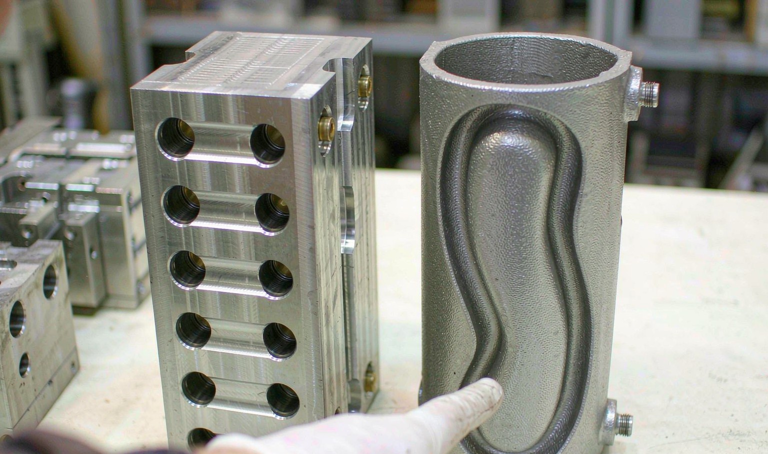
Cooling is a distance problem
A mould cools a part by conducting heat out through the steel to a channel of flowing water. The rate is set by how far the heat has to travel, and the relationship is not linear: cooling time goes with the square of that distance. Halve the distance and the time falls by four.
A drilled circuit cannot follow a contour. The bores are straight, they intersect at right angles, and each one has to be reachable by a drill from outside the block. That puts the channel on a grid, and the distance from any point on the cavity surface to the nearest water varies with position: 12 mm in the middle of a flat face, 30 mm or more in a deep corner or at the base of a tall core.
Conformal cooling is the obvious answer and the hard one: build the channel as a curve that holds a constant offset from the surface, usually 1.5 to 3 channel diameters, everywhere. It cannot be machined, so for decades it was not done. Additive manufacturing changed that, and a laser powder bed printer will now build a channel of any shape that does not need support.
What you get is a uniform distance, and a uniform distance means a uniform cooling rate. The cycle time saving is the headline. The warpage saving is often the bigger number, because a part that cools evenly comes out flat and a part that cools unevenly comes out with a twist that no amount of packing will remove.
What the gap is actually worth
The gain depends on the wall, and it grows with it. On a 1.5 mm wall a drilled circuit cools in about 12 s and a conformal one in 9. The part is thin enough that the heat is out before the channel distance has time to matter, so the saving is 3 s and 25 percent.
At 3 mm it is 50 s against 32. At 4 mm, 88 against 52. At 6 mm, 190 against 108. Both the absolute gap and the percentage widen, because a thick section is exactly the case where the channel distance dominates the resistance: 25 percent at 1.5 mm, 36 at 3, 41 at 4, 43 at 6.
That is why conformal cooling is a thick-wall technology. On a 1.2 mm housing the cycle is limited by the machine, the robot and the take-out, not by cooling, and a printed insert buys almost nothing. On a 4 mm lens or a 6 mm pipe fitting it buys half the cycle.

Three ways to get a conformal insert
Laser powder bed fusion in maraging steel is the default. A 20 to 50 micron layer, a build envelope of 250 to 400 mm, and a channel that can be any shape that does not need support. The as-built channel is rough at 8 to 14 microns Ra, which raises the pressure drop; a finished insert is honed, or the channel is chemically polished, or the whole thing is machined back to size after printing.
Binder jetting is faster and cheaper per cubic centimetre and produces a part that is slightly porous as built, so it has to be sintered or infiltrated to full density. It suits large, less critical inserts and prototypes of the circuit rather than production tooling.
The hybrid route is the pragmatic one: print only the core or the cavity shell that carries the channel, and bolt it into a conventionally machined frame that holds the ejectors, the slides and the mounting. It cuts the printed volume, and printed volume is what the price is made of. Most production conversions are hybrids.
| Route | Min channel | Lead time | Relative cost | Am besten für |
|---|---|---|---|---|
| Laser powder bed (1.2709) | 1.5 mm | 3-5 weeks | 100 | Production cores and cavities |
| Binder jet + sinter | 3 mm | 2-3 weeks | 70 | Large inserts, circuit trials |
| Hybrid printed shell | 1.5 mm | 3-4 weeks | 65 | Converting an existing tool |
| Drilled, conventional | 6 mm | 1-2 weeks | 35 | Thin walls, low volume |
Table 1 — Routes to a conformal circuit, with cost indexed on a printed production insert
Payback is a volume question
A printed insert set costs more than a drilled one, by a factor of two to three on the insert. That premium is paid once. The payback is the premium divided by the saving per part, and the saving per part is the cycle time saved multiplied by the machine rate.
Take a 3 mm wall part: 50 s of cooling becomes 32, so 18 s come off every cycle. On a machine costed at EUR 50 an hour, 18 s is EUR 0.25 a part. If the conformal set costs EUR 25,000 more than the drilled set, the break-even is 100,000 parts, and everything after that is cycle time you never pay for again.
Which is why the answer is about volume and not about technology. At 10,000 parts a year the premium takes 98 months to return. At 50,000 it is 25 months. At 200,000 it is eight months, and at a million it is two.
There is a second saving the curve does not show: the parts that are not scrapped for warpage. On a flat part with a tight flatness callout a conformal circuit can take the reject rate from 6 percent to under 1 percent, and at a high part value that alone moves the break-even by a year.
Where a printed insert does not help
Thin walls. Below about 2 mm the cooling time is short and the cycle is limited somewhere else. A printed insert on a 1.2 mm lid is money spent on the wrong constraint.
Low volume. Under 50,000 parts a year the premium is hard to recover unless the part value is high or the warpage scrap is severe. A bridge tool for a product launch is the wrong candidate.
Hard water. A printed channel cannot be brushed out. Scale in a 6 mm curved channel is a permanent loss of performance, because there is no straight run to rod and no access to the bend. A printed insert wants a closed loop with treated water and a filter, and that is a running cost to budget for.
Abrasive or corrosive resins. PVC and some filled grades attack steel, and the rough as-built channel holds the residue far better than a honed bore. A printed insert in a PVC tool needs a coating or it needs to be a different tool.
Parts where the channel cannot reach the problem. If the thick section is a boss on the back of the part and the cosmetic face is on the front, moving the channel closer to the cosmetic face does nothing for the boss. The wall map has to be read before the circuit is designed.
Specifying a conformal insert
Send the part, a wall thickness map, the current circuit drawing and the cycle. The wall map matters more than the drawing, because the channel should follow the thick sections rather than the surface, and on most parts those are not the same place.
Decide the offset deliberately. 1.5 diameters gives the fastest cooling and the least uniform tool temperature; 3 diameters gives a more uniform tool and a longer cycle. For a part with a tight flatness callout, uniform beats fast, and the extra seconds are bought back by the scrap that does not happen.
Decide the connection before the insert is built. A printed channel ends in a threaded port, and the port is the weak point: it is a machined feature in a printed wall, and a hose that pulls on it will leak. Plan the routing and the manifold block while the geometry is still on a screen.
| Decision | Option | Effect |
|---|---|---|
| Offset | 1.5 D / 3 D | Fast cycle against uniform tool |
| Channel diameter | 6 / 8 / 10 mm | Flow rate against pressure drop |
| Circuit | Series / parallel | Uniform flow against uniform temperature |
| Ports | Direct / manifold | Simplicity against hose routing |
| Oberfläche | As built / honed | Cost against pressure drop |
Table 2 — The decisions that have to be made before printing
How much cycle time does conformal cooling save?
Between 25 percent on a 1.5 mm wall and 43 percent on a 6 mm wall, for the same part on the same machine. The absolute seconds are what matter: three seconds on a thin part, eighty on a thick one.
Can any mould be converted?
The cavity or core insert can, if there is room for a printed shell inside a machined frame. A stack mould or a tool with complex slides usually is not worth converting, because the printed volume and the risk both go up.
What is a printed insert made from?
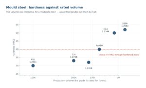
Maraging steel powder, 1.2709 or an equivalent, printed and then aged to about 50 HRC. Once it is solid it machines, polishes and textures like any other insert.
Does a printed channel need more pump pressure?
Typically 20 to 40 percent more, because the as-built surface is rough at 8 to 14 microns Ra. Honing or chemical polishing brings the pressure drop back close to a drilled channel.
How long does a printed insert last?
As long as a machined one in clean water. In hard water it is shorter, because the channel cannot be brushed out and scale is permanent. Treat the water and it stops being a factor.
What is the lead time?
Three to five weeks for printing, stress relief, finishing and fitting, on top of the tool design. A drilled insert is one to two weeks, so a conformal conversion adds roughly a month to a tool build.
A cycle that cooling is holding back?
Send the part, the wall map and the current cycle. We will tell you how much of it is cooling, what a conformal circuit would return, and at what volume it pays.





 DE
 EN
 ES
 FR
 PT
 AR
 RU
 JA
 KO
 IT
 NL
 TR
 PL
 ID
