

Two ways to add up a stack
A stack-up is a sum of variations along a dimension chain. If a shaft sits in a bearing in a housing and a cover closes on top, the gap at the cover depends on five dimensions, each with its own tolerance, and the question is how much of each tolerance survives to the gap.
There are two answers and they differ by a factor of two or more. The worst case method adds every tolerance arithmetically, which guarantees that no assembly can ever fail. The statistical method adds the squares and takes the square root, which gives a much smaller number and guarantees nothing, but predicts that a known fraction of assemblies will fail.
On the same five part stack, each at plus or minus 0.10 mm, worst case gives 0.50 mm and root sum square gives 0.224 mm. The gap between them is the safety factor you are buying, and it is bought with tighter tolerances on every part, which means more expensive tools.
Most production assemblies use the statistical method, because the worst case method is unaffordable and because the probability of all five parts arriving at their extreme simultaneously is small. That is a defensible engineering decision, but only if it is made explicitly and the resulting scrap rate is predicted and accepted.
Why worst case is not wrong
Worst case is the only method that needs no assumption about distributions. If every part is inside its tolerance, every assembly works. That property is worth a great deal in safety critical applications, in low volume production where a single failure is expensive, and in any assembly that cannot be adjusted at build.
It is also the right method when the number of parts is small. With two parts in the stack, worst case is 0.20 and RSS is 0.141, a difference of 0.06 mm. With twenty parts, worst case is 2.00 and RSS is 0.447, a difference of 1.55 mm. The statistical saving grows with the square root of the part count, so the argument for it strengthens as the stack gets longer.
The practical position most companies take is a hybrid. Worst case for safety functions and for anything that must never fail. Statistical for cosmetic gaps, for high volume assemblies and for stacks with more than about five parts, with a documented scrap allowance.
What is not defensible is to use RSS because it makes the drawing pass, and then to be surprised when 2 percent of assemblies need rework. The RSS number is a prediction, and a prediction that nobody wrote down cannot be checked.
Root sum square and what it assumes
RSS assumes three things. Each dimension varies normally about its nominal. Each dimension is independent of the others. Each process is centred on nominal, or at least has a known offset that is being handled separately. When all three hold, the assembly dimension is also normal, and its standard deviation is the root sum square of the individual standard deviations.
The tolerance is then set as a multiple of that standard deviation. A plus or minus 3 sigma limit contains 99.73 percent of assemblies; 4 sigma contains 99.994 percent. Most companies use 3 sigma and accept roughly three failures per thousand, which for a moulded assembly is usually absorbed by a functional test or an adjustment step.
The assumption that fails most often is independence. Two dimensions moulded in the same tool from the same cavity are correlated through the tool wear, the mould temperature and the material batch. Treating them as independent underestimates the total variation, sometimes badly.
The second assumption that fails is centring. A dimension that runs 0.05 mm off nominal because the tool was cut that way is not centred, and its whole tolerance band sits to one side. RSS assumes symmetry, so an offset dimension needs to be handled as a mean shift plus a variation, not as a symmetric tolerance.
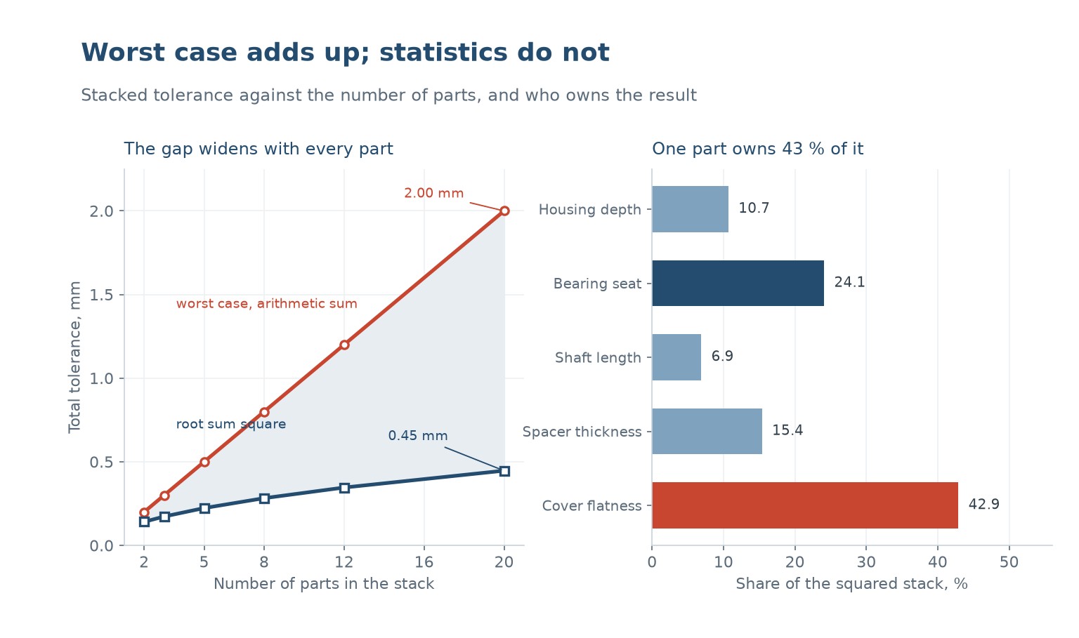
The part that owns the result
In an RSS stack, each part contributes its tolerance squared. That means a part with twice the tolerance of another contributes four times as much, and the largest tolerance in the stack usually dominates the result far more than intuition suggests.
On the five part stack in the chart, the cover flatness at plus or minus 0.20 mm contributes 42.9 percent of the squared total, while the shaft length at plus or minus 0.08 mm contributes 6.9 percent. Tightening the shaft would be almost pointless. Halving the cover tolerance would cut the total RSS from 0.224 to about 0.19 mm, a 15 percent improvement for one change.
That is the most useful output of a stack-up: not the total, but the ranking. It tells you where the money goes. A tool modification on the dominant part is usually cheaper than tightening four other parts, and it is often cheaper than the inspection that would otherwise be added to catch the failures.
The ranking also changes as the design changes. A part that dominates at five components may become minor at eight, and a new part with a loose tolerance can take over the top of the list. Re-running the calculation after every design change is a ten minute job that prevents a surprise at first article.
Where the numbers come from
A stack-up is only as good as its inputs, and the inputs are usually optimistic. A moulded part tolerance is not the drawing tolerance, it is what the process actually holds over a year of production, including tool wear, material batch variation and machine drift.
The honest source is a capability study. Take thirty parts from three shots across a shift, measure the dimension, and calculate the standard deviation. A process running at Cpk 1.33 holds plus or minus 4 sigma inside its tolerance, which means the drawing tolerance is being used at three quarters of its width. A process at Cpk 1.0 is using the whole band and will produce out of tolerance parts every day.
For a new part with no history, the fallback is the material and process table. An unfilled thermoplastic in a well controlled tool holds plus or minus 0.05 mm on a dimension under 50 mm and plus or minus 0.1 percent above that. A glass-filled grade adds 50 percent. A dimension across a parting line adds more again, because it depends on two tool halves aligning.
| Dimension type | Typical capability | What drives it |
|---|---|---|
| Moulded, single cavity, under 50 mm | Plus or minus 0.05 mm | Tool machining and material shrink |
| Moulded, single cavity, over 50 mm | Plus or minus 0.1 % of the dimension | Shrink variation across the part |
| Moulded, multi-cavity | Plus or minus 0.08 mm | Cavity to cavity difference |
| Across a parting line | Plus or minus 0.12 mm | Two tool halves aligning |
| Glass filled material | Add 50 % to the above | Fibre orientation changes shrink |
| Assembled with a screw | Plus or minus 0.15 mm | Clearance in the hole |
Table 1 — Realistic tolerance inputs for a moulded assembly
Designing to the stack, not to the part
The most useful thing a stack-up does is change the design before the tool is cut. If the calculation shows the gap will be 0.5 mm plus or minus 0.3, there are three responses: tighten the dominant part, add an adjustment feature, or accept the variation and design the gap to look intentional.
The adjustment feature is often the cheapest. A slotted hole instead of a round one, a shim washer, a snap feature with a range of engagement, or a screw that pulls two parts together all absorb variation at assembly for almost no tool cost. They are unfashionable because they look like a compromise, and they are usually the right answer.
Designing the gap to look intentional is the third option and the one that is most often overlooked. A 0.5 mm gap that varies by 0.3 mm looks like a defect if the nominal is zero and like a design feature if the nominal is 0.8 mm with a shadow line. The stack-up did not change, the perception did.
What does not work is specifying a tight tolerance on the drawing and hoping. A plus or minus 0.02 mm tolerance on a moulded dimension over 100 mm is not achievable in production, and a supplier who accepts it will either fail at first article or inspect every part and charge for it.
What to do when the stack fails
When the calculation shows the assembly will not work, the first question is whether the failure is in the nominal or in the variation. A nominal failure means the parts cannot fit even at their exact nominal dimensions, which is a design error and needs a geometry change. A variation failure means the parts fit on average and sometimes do not, which is a tolerance problem.
The second question is whether the failing dimension is measurable at assembly. A gap that can be checked with a feeler gauge and adjusted is a different problem from a gap that is only discovered when the customer complains. Adding a 100 percent check is expensive; adding an adjustment is usually cheaper.
The third question is what the failure actually costs. A 2 percent rework rate on a low volume assembly may be cheaper than tightening three tools. On a high volume line the same 2 percent is a full time rework station, and the tool change pays back in months.
| Situation | First response | لماذا |
|---|---|---|
| Nominal does not fit | Change the geometry | No tolerance can fix a negative nominal gap |
| RSS passes, worst case fails | Document the risk and the predicted scrap | This is a deliberate decision, not an accident |
| One part dominates the stack | Tighten or redesign that part only | The squared contribution makes it the cheapest lever |
| Correlated dimensions | Use worst case for those, RSS for the rest | Independence is the assumption that breaks |
| Offset from nominal | Handle the mean shift separately | A symmetric band around an offset centre is misleading |
| Failure only at temperature extremes | Add the thermal term explicitly | Shrink and expansion are not in the drawing |
Table 2 — Reading a failed stack-up
Should I use worst case or RSS?
Worst case for safety functions, for low volume and for stacks of three parts or fewer. RSS for cosmetic gaps, high volume and longer stacks, with the predicted failure rate written down and accepted. Many companies use both and take the worst case for the critical dimensions only.
How many parts make RSS worth using?
The saving grows with the square root of the part count, so the argument strengthens quickly. At two parts the difference is small; at five it is a factor of two; at twenty it is a factor of four. Above about five parts, RSS is almost always worth calculating.
Where do I get the tolerance for a new moulded part?
From a capability study if the part exists, and from a material and process table if it does not. A single cavity unfilled part holds about plus or minus 0.05 mm under 50 mm; above that, use 0.1 percent of the dimension. Add 50 percent for glass filled, and more for dimensions across a parting line.
Why does my stack-up pass on paper and fail in production?
Usually one of three things: the input tolerances were drawing tolerances rather than capability, a dimension was correlated with another and treated as independent, or a dimension is offset from nominal and was treated as symmetric. Check all three before changing a tool.
Does the assembly method belong in the stack?
Yes. A screw in a clearance hole adds its own variation, a snap fit has an engagement range, and an adhesive joint has a bond line thickness. Leaving the assembly out of the stack is the most common reason a calculation that looked fine produces parts that do not fit.
Can a stack-up be done after the tool is cut?
It can, and it is worth doing, but the options are limited to adjustment features and sorting. The geometry is fixed, so the only levers are the assembly method and the inspection plan. That is why the calculation belongs before the tool, where a change costs a drawing revision rather than a tool revision.
Assembly not closing on the drawing?
Send the dimension chain, the part drawings and the assembly method. We will run the stack-up both ways and tell you which part to change.




 AR
 EN
 ES
 FR
 DE
 PT
 RU
 JA
 KO
 IT
 NL
 TR
 PL
 ID
