
Where the thrust comes from
The screw generates pressure to push melt through the die, and that pressure acts on the screw flights as an axial force. The force is the pressure multiplied by the projected area of the flights, which is why it rises with the square of the screw diameter.
That force is transmitted through the screw shank into the thrust bearing in the gearbox. The gearbox is designed for it, but the rating assumes a maximum head pressure that the machine was sold with, and that number is often exceeded in service.
A screen pack that has blinded, a cold die, a high viscosity resin run below its normal temperature and a long die land all raise head pressure. Each of them is a normal operating condition, and each of them loads the thrust bearing harder than the design case.
The bearing does not fail suddenly. It fatigues, and fatigue life falls roughly with the cube of the load, which means a 20 percent overload costs more than half the life.
Why diameter matters so much
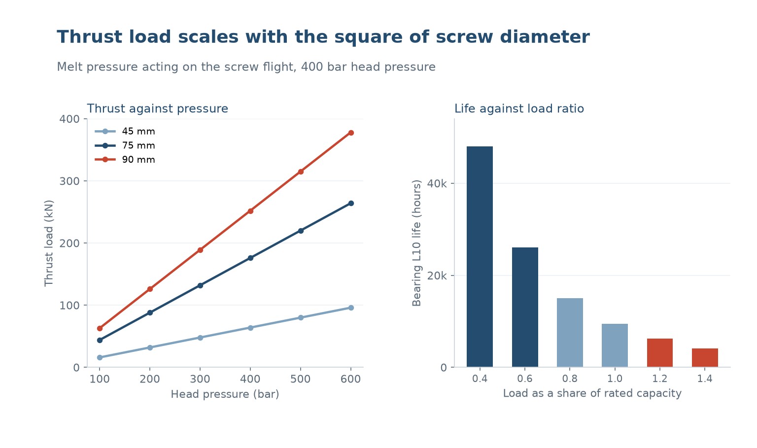
The chart on the left is thrust load against head pressure for 45, 75 and 90 mm screws. At 400 bar the 45 mm screw sees 64 kilonewtons, the 75 mm sees 176 and the 90 mm sees 252.
The ratio between the 45 and the 90 is almost exactly four, which is the square of the diameter ratio. That is the whole scaling law, and it explains why a small extruder can run at very high head pressure while a large one cannot.
It also explains why an operator who moves from a 45 mm line to a 90 mm line and keeps the same die can destroy a gearbox. The die that produced 300 bar on the small machine produces the same pressure on the large one, but the thrust is four times higher.
The right hand panel is bearing life against load ratio. At 0.4 of rated capacity the L10 life is 48,000 hours, at 0.8 it is 15,000, at 1.0 it is 9,500 and at 1.4 it is 4,100. Running at rated capacity is not a design point, it is a wear-out point.
What raises head pressure
The screen pack is the most common cause because it changes continuously. A clean pack might cost 20 bar; a blinded one can cost 150. If the machine has no pressure feedback to the operator, the pack is changed on schedule rather than on condition, and it spends part of its life heavily loaded.
Die restriction is the second. A die designed for one product run on another, or a die with a partially blocked flow channel, raises pressure across the whole line.
Resin temperature is the third. Running below the recommended profile raises viscosity and therefore pressure. An operator chasing a surface finish by dropping temperatures can add 50 to 100 bar without realising it.
Output rate is the fourth, because pressure rises with flow through a fixed restriction. Running a line above its rated output to meet a delivery is a common way to overload a gearbox quietly.
| السبب | Typical pressure change | Detection |
|---|---|---|
| Clean to blinded screen pack | +20 to +150 bar | Melt pressure gauge trend |
| Wrong die for the product | +50 to +120 bar | Compare to die datasheet |
| Temperature too low | +50 to +100 bar | Check profile against spec |
| Output above rating | +30 to +80 bar | Compare rate to nameplate |
| Cold start | Very high briefly | Interlock on melt temperature |
Table 1 — What actually loads the thrust bearing.
Protecting the gearbox
A melt pressure transducer between the screw and the die is the primary protection. It should be interlocked to stop the screw at a set pressure, not merely displayed. A display that nobody watches is not protection.
A bursting disc or a pressure relief in the die is the secondary protection. It is a consumable and it should be replaced on schedule rather than after it fails.
A cold start interlock prevents the most damaging event. Starting a screw in cold polymer produces a pressure spike that can exceed the gearbox rating in under a second, and it is the usual cause of a gearbox failure that cannot be explained afterwards.
A maintenance schedule on the thrust bearing is the third. Record the oil analysis, the vibration signature and the axial play, and replace the bearing on condition rather than on failure.
| Protection | النوع | What it prevents |
|---|---|---|
| Melt pressure transducer | Interlocked trip | Sustained overload |
| Bursting disc | Mechanical relief | Pressure spike damage |
| Cold start interlock | Temperature based | Start-up spike |
| Oil analysis | Condition monitoring | Bearing wear detection |
| Vibration monitoring | Condition monitoring | Early bearing failure |
Table 2 — Layers of gearbox protection, cheapest first.
Sizing a gearbox for the real duty
Size on the maximum head pressure the process will ever demand, not the typical one, and then apply a margin. A gearbox selected at 100 percent of the calculated maximum will spend its life at the fatigue limit.
A reasonable target is to run at 70 to 80 percent of the rated thrust in normal operation, which leaves room for a blinded screen pack and a cold morning without eating the bearing life.
Check the torque rating separately. Thrust and torque are different limits, and a gearbox can be comfortable on one and marginal on the other. High pressure at low speed loads thrust; high output at high speed loads torque.
Finally, check the service factor the manufacturer applied. A service factor of 1.0 is a laboratory number; a real extrusion line wants 1.4 or more on a continuous duty application.
Symptoms of an overloaded gearbox
The first is noise. A thrust bearing at the end of its life makes a low frequency rumble that changes with load, and it is often attributed to the gear mesh until the bearing fails.
The second is temperature. Gearbox oil temperature rising above its normal band at constant load indicates increased friction, which is either bearing wear or lubricant breakdown.
The third is axial movement. A dial indicator on the screw shank will show end float beyond specification when the thrust bearing is worn, and that movement translates directly into unstable output.
The fourth is metal in the oil. Oil analysis catches bearing wear before any of the other symptoms appear, which is why it is the cheapest monitoring available.
How does head pressure load an extruder gearbox?
Melt pressure acts on the screw flights and produces an axial force that the thrust bearing must absorb. The force is pressure times the projected flight area.
Why does thrust scale with the square of screw diameter?
Because the projected area of the flights scales with diameter squared. A 90 mm screw sees about four times the thrust of a 45 mm screw at the same pressure.
What head pressure is safe for an extruder?
Run at 70 to 80 percent of the gearbox rated thrust in normal operation. That leaves margin for a blinded screen pack or a cold start without consuming bearing life.
How does overload affect bearing life?
Fatigue life falls roughly with the cube of the load. At 1.4 times rated capacity the L10 life is about 4,100 hours against 48,000 at 0.4.
What causes a sudden gearbox failure?
A cold start is the usual cause. Starting the screw in solid polymer produces a pressure spike that can exceed the rating in under a second, which is why a temperature interlock matters.
How do I know the gearbox is overloaded?
Low frequency rumble that changes with load, rising oil temperature at constant load, axial end float on the screw, and metal in the oil analysis.
Running at high head pressure?
Send the screw diameter, the die and the normal pressure reading. We will tell you how much thrust margin you actually have.





 AR
 EN
 ES
 FR
 DE
 PT
 RU
 JA
 KO
 IT
 NL
 TR
 PL
 ID
