
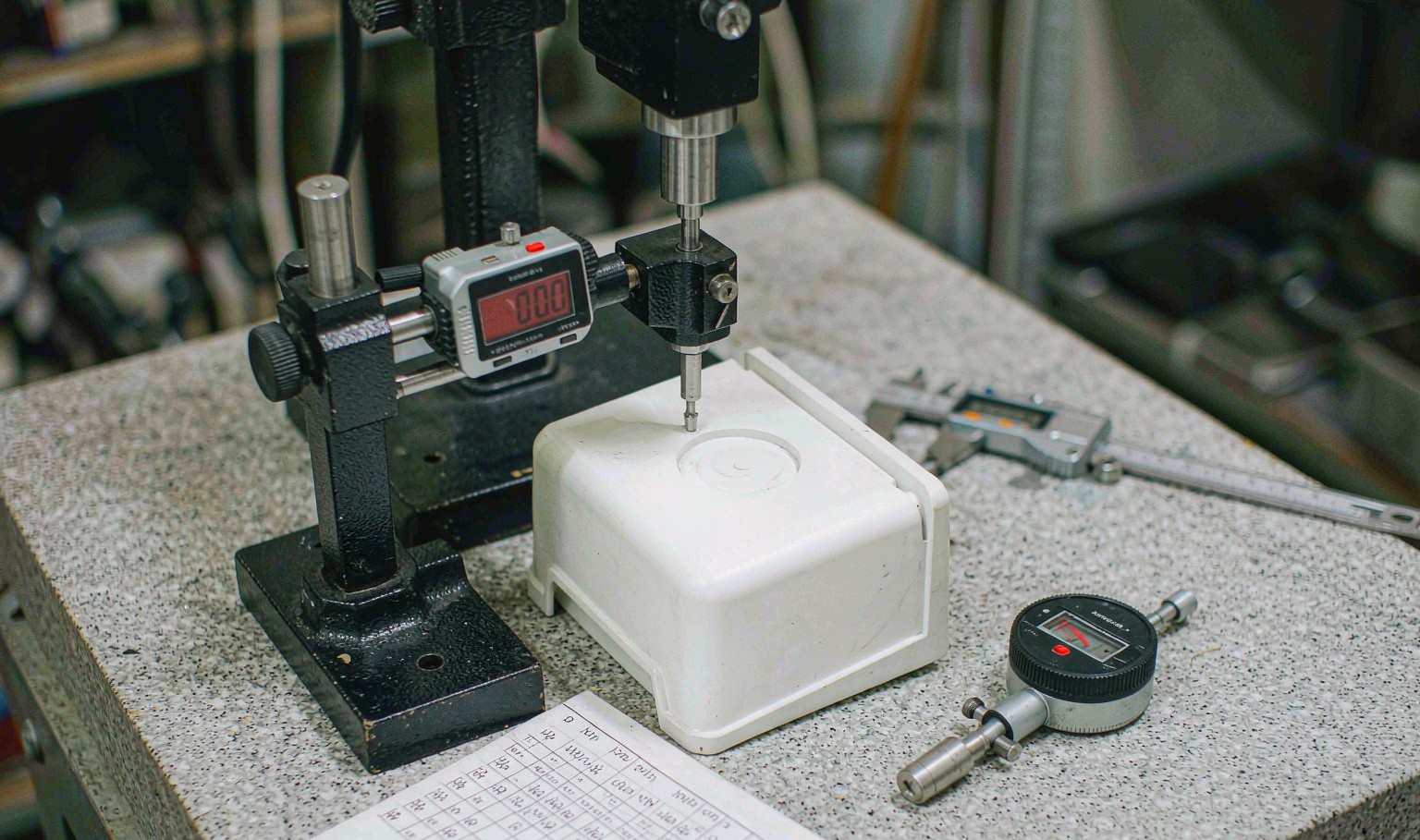
- 1. 1. The myth of "the moulding tolerance"
- 2. 2. Four sources of dimensional variation
- 3. 3. Shrinkage: the number that is never one number
- 4. 4. Tolerance grades and how to use them
- 5. 5. Achievable tolerance by feature type
- 6. 6. Tolerance by material
- 7. 7. Datums, and why most disputes start here
- 8. 8. What Cpk actually tells you
- 9. 9. What tight tolerances cost
- 10. 10. Measuring a moulded part properly
- 11. 11. How to write a tolerance block that works
- 12. 12. Frequently asked questions
- 13. Send the drawing — we will tell you which tolerances are real
On this page
- The myth of "the moulding tolerance"
- Four sources of dimensional variation
- Shrinkage: the number that is never one number
- Tolerance grades and how to use them
- Achievable tolerance by feature type
- Tolerance by material
- Datums, and why most disputes start here
- What Cpk actually tells you
- What tight tolerances cost
- Measuring a moulded part properly
- How to write a tolerance block that works
- Frequently asked questions
1. The myth of "the moulding tolerance"
Search for injection moulding tolerances and you will find tables that say things like "±0.05 mm for dimensions under 10 mm, ±0.10 mm for 10 – 100 mm". These tables are not wrong, but they are misleading in a specific way: they describe what a well-controlled process can achieve on a favourable feature, and they get copied into drawings as though they were a promise.
The honest statement is that tolerance is a function of five things at once — the material, the part geometry, the tool, the machine and the process control — and no single table can account for all of them. Two parts with the same nominal dimension can differ by a factor of five in achievable tolerance because one has a dimension across a parting line and the other has a dimension on a ground core pin.
The question to ask instead. Not "what tolerance can you hold?" but "what tolerance can you hold on this feature, in this material, at this wall thickness, on this tool?" A supplier who answers the first question with a single number is answering a different question than the one you asked.
2. Four sources of dimensional variation
Every deviation from nominal on a moulded part comes from one of four sources. Separating them is the whole of tolerance engineering, because each one is fixed differently.
Tool variation
The steel is machined to a nominal that already includes a shrinkage allowance. Tool variation is the sum of machining accuracy, EDM accuracy, fitting tolerance between cavity and core, and wear over the life of the tool. It is essentially fixed at build and then drifts slowly.
Typical tool-only variation on a well-built tool: ±0.02 – 0.05 mm on a machined dimension, ±0.01 mm on a ground dimension. This is the floor of what the process can ever achieve, because the process cannot correct for steel that is in the wrong place.
Shrinkage variation
Plastic shrinks as it cools, and the amount depends on the material, the wall thickness, the flow orientation, the packing pressure and the cooling rate. A tool cut for 0.5 % shrinkage will produce parts that are 0.45 % small on one dimension and 0.55 % on another, because the two dimensions did not see the same conditions. This is usually the largest single contributor on a new part.
Process variation
Cycle-to-cycle variation from melt temperature drift, hydraulic response, packing pressure variation, cooling time tolerance and ambient conditions. On a stable machine running a stable process this is small — a few hundredths of a millimetre. On a machine shared between jobs, with the process adjusted by whoever is on shift, it can be ten times larger.
Measurement variation
How the part is measured, at what temperature, with what instrument, by whom. A flexible part measured with a caliper under hand pressure reads differently from the same part on a CMM. A part measured straight off the machine, still warm, is larger than the same part measured the next day. This source is routinely ignored and it accounts for a surprising share of "the parts are out of tolerance" conversations.
| المصدر | Typical magnitude | Fixed by | When it changes |
|---|---|---|---|
| Tool machining and fitting | ±0.02 – 0.05 mm | Tool build quality | Fixed at build, drifts with wear |
| الانكماش | 0.3 – 0.8 % of dimension | Material choice, wall design, gate position | Constant per tool, varies per dimension |
| العملية | ±0.02 – 0.15 mm | Machine condition, process control, SPC | Every shift if uncontrolled |
| Measurement | ±0.01 – 0.10 mm | Fixture, method, temperature, operator | Every inspection |
Shrinkage scales with the dimension; the other three are closer to absolute. That is why large parts need percentage-based tolerances, not fixed ones.
3. Shrinkage: the number that is never one number
Every material datasheet gives a shrinkage value, usually a range like 1.4 – 2.0 %. What the datasheet does not say is that the value depends on wall thickness and flow direction, and that a tool designed to the midpoint of the range will be wrong on some dimensions.
| المواد | Datasheet shrinkage | Directional difference | Practical note |
|---|---|---|---|
| PP homopolymer | 1.5 – 2.5 % | 0.3 – 0.5 % higher across flow | Highest of the commodity resins; thick walls shrink more |
| البولي إيثيلين عالي الكثافة | 1.5 – 3.0 % | 0.3 – 0.6 % | Very wall-thickness sensitive |
| ABS | 0.4 – 0.7 % | 0.1 – 0.2 % | Low and fairly predictable |
| HIPS | 0.4 – 0.7 % | 0.1 – 0.2 % | Similar to ABS |
| كمبيوتر شخصي | 0.5 – 0.7 % | 0.1 – 0.2 % | Low, but stress-sensitive |
| PC/ABS | 0.5 – 0.7 % | 0.1 – 0.2 % | Good dimensional stability |
| ب م أ م أ | 0.3 – 0.6 % | 0.1 – 0.2 % | Lowest of the common resins |
| PA6 (dry) | 0.8 – 1.5 % | 0.3 – 0.5 % | Plus moisture swelling after moulding |
| PA66 (dry) | 1.0 – 2.0 % | 0.3 – 0.6 % | Plus moisture swelling, up to 0.5 % |
| POM | 1.8 – 2.2 % | 0.2 – 0.4 % | High but consistent; excellent for precision gears |
| PBT | 1.5 – 2.0 % | 0.2 – 0.5 % | Drops sharply with glass loading |
| PA66 + 30 % GF | 0.3 – 0.6 % | 0.2 – 0.4 % | Flow direction shrinks far less than across flow |
| PPS + 40 % GF | 0.2 – 0.4 % | 0.1 – 0.3 % | Very low, very anisotropic |
Directional difference means the part shrinks more across the flow direction than along it. On a long, flow-oriented part this alone can consume the whole tolerance.
Three practical consequences follow.
Shrinkage is not linear with wall thickness. A 2 mm wall and a 3 mm wall in the same material do not shrink by the same percentage — the thicker section shrinks more, because it stays hot longer and has more material to contract. A part with mixed wall thickness will have dimensions that drift in different directions.
Glass-filled materials are anisotropic. Glass fibres align with the flow, and the resin shrinks much less along the fibres than across them. A 30 % glass-filled PA66 part can shrink 0.3 % along the flow and 0.8 % across it. If the tool is cut to a single shrinkage value, one direction will be out of tolerance no matter what the process does.
Polyamides keep moving after they leave the machine. PA6 and PA66 absorb moisture from the air, and a dry-as-moulded part grows by 0.3 – 0.5 % over the first weeks until it reaches equilibrium. A part that measures in tolerance on the day it is moulded can be out of tolerance after a month in a humid warehouse. For precision PA parts, the drawing has to state the condition — dry as moulded, or conditioned.
4. Tolerance grades and how to use them
The two systems you will meet are DIN 16742 (now largely superseded by ISO 20457) and the supplier-specific tables that grew out of them. Both work the same way: a tolerance grade is selected from a table based on the nominal dimension and the material group, and the grade accounts for the fact that shrinkage variation scales with size.
| Nominal dimension | Grade 1 (tight) | Grade 2 (normal) | Grade 3 (relaxed) |
|---|---|---|---|
| up to 3 mm | ±0.05 | ±0.08 | ±0.12 |
| 3 – 6 mm | ±0.06 | ±0.10 | ±0.15 |
| 6 – 10 mm | ±0.08 | ±0.12 | ±0.18 |
| 10 – 18 mm | ±0.10 | ±0.15 | ±0.22 |
| 18 – 30 mm | ±0.12 | ±0.18 | ±0.28 |
| 30 – 50 mm | ±0.15 | ±0.22 | ±0.35 |
| 50 – 80 mm | ±0.18 | ±0.28 | ±0.45 |
| 80 – 120 mm | ±0.22 | ±0.35 | ±0.55 |
| 120 – 180 mm | ±0.28 | ±0.45 | ±0.70 |
| 180 – 250 mm | ±0.35 | ±0.55 | ±0.90 |
| 250 – 315 mm | ±0.45 | ±0.70 | ±1.10 |
Indicative values for unfilled commodity and engineering resins, single-cavity tool, controlled process. Glass-filled and semi-crystalline resins move one grade; dimensions across a parting line or on a slide move one grade.
Grade 2 is the sensible default for a general mechanical part. Grade 1 is for dimensions that are functionally critical and is a deliberate commercial decision — it usually implies a single-cavity tool, a dedicated machine, SPC and a first-article inspection report. Grade 3 is for dimensions nobody will ever measure, and specifying it honestly saves money.
The trap is that most drawings use a single general tolerance block for everything, so a dimension that could be ±0.5 mm is specified at ±0.1 mm along with the one dimension that genuinely needs it. That is how a straightforward part gets quoted as a precision part.
5. Achievable tolerance by feature type
The feature type matters more than the dimension. Two dimensions of the same nominal size can differ by a factor of three in achievable tolerance depending on how the steel that forms them is made and how the part releases from it.
| الميزة | Achievable | لماذا |
|---|---|---|
| Dimension within one cavity half, formed by one steel block | ±0.05 mm | Single machined feature, no stack-up |
| Dimension across the parting line | ±0.10 – 0.15 mm | Two halves, two machining setups, closing tolerance |
| Dimension formed by a slide | ±0.15 – 0.20 mm | Slide fit clearance plus wear over tool life |
| Dimension on a ground core pin (bore diameter) | ±0.03 – 0.05 mm | Ground steel, not milled |
| Depth of a blind pocket | ±0.10 mm | Depends on the end mill and the EDM burn |
| Concentricity of a boss to a bore | 0.05 – 0.10 mm TIR | Cavity and core alignment, plus shrinkage differential |
| Flatness of a large panel | 0.2 – 1.0 mm | Warpage dominates; tool accuracy is irrelevant here |
| Position of a feature on a warped part | ±0.20 mm | Warpage moves the feature, not the steel |
| Wall thickness | ±0.05 mm | Set by cavity/core gap, very stable |
| Angle or draft | ±0.5° | Difficult to measure, rarely worth tolerancing |
| Gate vestige height | 0.05 – 0.10 mm | Depends on gate type and degating method |
Note how flatness and warpage sit outside the pattern. They are not tool tolerances at all — they are process and design outcomes, and no amount of tool precision fixes them.

The parting line row deserves emphasis because it is the most common source of unplanned variation. A dimension that crosses the parting line is formed by two steel blocks that have to meet. The closing tolerance, the wear on the leader pins, the clamp force distribution and the thermal expansion of each half all contribute. If a critical dimension crosses the parting line, consider redesigning so it does not.
6. Tolerance by material
Material affects tolerance through shrinkage magnitude, shrinkage anisotropy, moisture absorption and stiffness. A flexible part is also harder to measure, which is a tolerance problem in its own right.
| Material group | Tolerance modifier | Reason |
|---|---|---|
| Amorphous, unfilled (ABS, PS, PC, PMMA, PC/ABS) | Base | Low, fairly isotropic shrinkage |
| Semi-crystalline, unfilled (PP, PE, POM, PA, PBT) | +1 grade | Higher shrinkage, more wall-thickness sensitivity |
| Glass or mineral filled | +1 grade | Anisotropic shrinkage, fibre orientation |
| Polyamides (PA6, PA66, PA11, PA12) | +1 grade, plus conditioning | Moisture absorption changes dimensions after moulding |
| Elastomers / TPE | +2 grades | Flexible, hard to measure, high shrinkage |
| High-aspect fillers (long glass, carbon fibre) | +2 grades | Strong directional shrinkage, warpage |
The modifier stacks with the feature modifier. A glass-filled PA66 dimension across a parting line is a grade 3 dimension, not a grade 1 dimension, no matter how it is drawn.
For elastomers the measurement problem is as significant as the shrinkage. A TPE part measured with a caliper compresses under the jaw, and two inspectors will get different numbers from the same part. TPE tolerances should be agreed with a specified measuring method — usually a non-contact optical measurement or a fixture that controls the compression.
7. Datums, and why most disputes start here
A tolerance is meaningless without a datum. If a drawing says a hole must be within ±0.1 mm of something, that something has to be a feature that exists on the part, is stable, and is accessible to the inspector.
The failure mode is common: the drawing dimensions everything from a theoretical centre or from a feature that is itself toleranced, so the inspector has to choose a reference, and their choice differs from the designer's assumption. The part then "fails" inspection even though nothing is wrong with it.
- Choose mouldable datums. A flat face, a moulded boss, a machined-in step. Not a centreline through a curved surface, and not a feature that warps.
- State the primary, secondary and tertiary datum explicitly. A three-plane datum scheme removes almost all ambiguity.
- Put the datum on the functional surface. If the part locates on a specific face in the assembly, that face is the datum — not the opposite face that happens to be flatter.
- Watch out for datums on warped features. If the primary datum is a large flat panel that warps 0.5 mm, every dimension measured from it inherits that variation.
A practical test. Before releasing a drawing, hand it to someone who has not seen the part and ask them to write down how they would measure three of the toleranced dimensions. If their answers differ from yours, the drawing is ambiguous, and the tool will be built to an interpretation you did not intend.
8. What Cpk actually tells you
A first-article inspection report tells you whether the parts you measured were in tolerance. It does not tell you whether the process will stay in tolerance. That is what Cpk measures, and it is the number worth asking for on a critical dimension.
Cpk compares the tolerance width to the process spread, centred on the nominal. A Cpk of 1.33 means the process spread is about three-quarters of the tolerance width and the process is centred — roughly 60 parts per million outside the limits if the distribution is normal. A Cpk of 1.0 means the spread equals the tolerance, and you should expect about 2,700 ppm out of tolerance.
| Cpk | Process spread vs tolerance | Approximate defect rate | Verdict |
|---|---|---|---|
| 0.67 | Spread is 1.5 × tolerance | ~45,000 ppm | Not capable |
| 1.00 | Spread equals tolerance | ~2,700 ppm | Marginal |
| 1.33 | Spread is 0.75 × tolerance | ~63 ppm | Normally acceptable |
| 1.67 | Spread is 0.6 × tolerance | ~0.6 ppm | جيد |
| 2.00 | Spread is 0.5 × tolerance | ~0.002 ppm | Excellent, rarely justified |
Values assume a normal distribution and a centred process. Moulding processes are often not perfectly normal, so treat the defect rates as indicative rather than exact.
For most moulded parts, Cpk 1.33 on the two or three genuinely critical dimensions is the right target. Demanding Cpk 1.67 on everything is a way of paying for process control you do not need.
9. What tight tolerances cost
Tolerance is not free, and the cost is not linear. Halving a tolerance typically doubles or triples the cost of holding it, because each step requires a different class of tool, machine and control.
| Tolerance band | What it requires | Relative cost impact |
|---|---|---|
| ±0.25 mm or looser | Standard tool, standard process | Baseline |
| ±0.15 mm | Better tool, documented process settings | +5 – 15 % |
| ±0.10 mm | Single-cavity tool or cavity-matched tool, process monitoring | +15 – 35 % |
| ±0.05 mm | Ground steel, single cavity, dedicated machine, SPC, 100 % inspection | +40 – 100 % |
| below ±0.05 mm | Often not moulding at all — consider machining or post-processing | +100 % and up |
Cost impact includes tool, piece price and inspection. On a high-volume part the inspection cost alone can exceed the tool cost difference.
Multi-cavity tools add a specific problem: cavities are not identical. Two cavities cut to the same nominal can differ by 0.02 – 0.05 mm because of machining and fitting, and they can shrink differently because their cooling circuits are not thermally identical. On a ±0.05 mm dimension, an eight-cavity tool is eight separate processes that all have to be capable. This is why precision parts are usually single-cavity even when the volume justifies more.
10. Measuring a moulded part properly
A large share of tolerance disputes are measurement disputes. Four practices remove most of them.
Measure at a defined time and condition. Plastic parts continue to shrink and, for polyamides, to absorb moisture for hours or days after moulding. State whether the measurement is at 1 hour, 24 hours or 48 hours, and at what temperature and humidity. For PA parts, state whether the part is dry or conditioned.
Use a fixture for flexible parts. A caliper on a TPE or thin-wall part reads whatever the operator's hand pressure produces. A simple gauge that locates on the datum features gives repeatable numbers; a caliper does not.
Match the instrument to the tolerance. A caliper resolves 0.01 mm but its practical accuracy on a plastic part is closer to ±0.05 mm. Measuring a ±0.05 mm tolerance with a caliper is measuring noise. Use a micrometer, a height gauge on a granite plate, or a CMM.
Agree the measurement method in writing before the first article. Which dimensions, which instrument, which datums, at what time after moulding, and who signs off. A first-article report without an agreed method is an opinion.
11. How to write a tolerance block that works
Most tolerance problems are created on the drawing, before anyone touches steel. A tolerance block that works has four properties.
- One general tolerance, honestly chosen. Put the realistic general tolerance in the title block — usually grade 2 or grade 3 — and then call out the handful of dimensions that need better. This is the opposite of the common practice, which is to put ±0.05 mm in the title block and then argue about it.
- Functional tolerances only. Tolerance a dimension because something fits, seals, moves or is measured by the customer. If nothing depends on it, it does not need a tolerance.
- Stated datums. Three planes, explicitly marked, on features that exist and do not warp.
- Stated condition. Material, moisture condition, time after moulding, and the measurement standard for anything flexible.
A useful discipline is to mark each toleranced dimension with the reason it is toleranced — "seal groove", "bearing seat", "mates with part 2". When the toolmaker asks why a dimension is ±0.05 mm, the answer is in the drawing rather than in someone's memory, and when the part fails inspection everyone can see what actually matters.
What we ask for. Send the drawing with the general tolerance block and the critical dimensions identified. We will tell you which of the critical ones are achievable on the proposed tool, which need a different tool configuration, and which could be relaxed without affecting function — before the quotation, not after the first article.
12. Frequently asked questions
What is a normal tolerance for injection molded parts?
±0.10 mm on general dimensions of a small part in an unfilled resin, widening to ±0.25 mm or ±0.1 % on parts over 200 mm. That is grade 2 in DIN 16742 terms and it covers the large majority of mechanical and consumer parts. Anything tighter should be justified by function.
Can injection molding hold ±0.02 mm?
Rarely, and not as a general tolerance. It is achievable on a specific feature — a ground core pin diameter, for example — in a single-cavity tool with a dedicated machine and full SPC. As a general tolerance across a part it is not realistic; the shrinkage variation alone usually exceeds it.
Why do my parts measure differently at the supplier and at goods-in?
Almost always a measurement or condition difference: measured at different times after moulding, at different temperatures, with different instruments, or against different datums. Polyamide parts also change dimension as they absorb moisture. Agree the method, the timing and the datums in writing and the discrepancy usually disappears.
Does adding cavities reduce achievable tolerance?
Yes, on tight dimensions. Each cavity is a separate piece of steel with its own machining and fitting variation, and its own cooling. On ±0.10 mm the effect is usually absorbed; on ±0.05 mm, multi-cavity tools frequently cannot hold all cavities in tolerance without cavity matching and individual process tuning.
How much does a tighter tolerance cost?
Going from ±0.25 mm to ±0.10 mm typically adds 15 – 35 % across tool, piece price and inspection. Going to ±0.05 mm can double the cost, because it usually requires a single-cavity tool, a dedicated machine and 100 % inspection.
Should I tolerance wall thickness?
Usually not as a dimensional tolerance. Wall thickness is set by the cavity-to-core gap and is one of the most stable features on a moulded part — typically ±0.05 mm. Specify a nominal wall and a maximum, and leave the rest to the general tolerance block.
What about flatness on large panels?
Flatness is a warpage outcome, not a tool tolerance, so it is the hardest thing on the drawing to guarantee. Realistic values are 0.2 – 0.5 mm on a stiff, well-ribbed panel and 0.5 – 1.0 mm on a large flat panel with no ribs. If flatness is critical, the design needs ribs, uniform wall and balanced cooling — and the drawing should state the measurement method, because flatness measured on a constrained part is not flatness.
Do you provide first-article inspection reports?
Yes. We provide a dimensional report against the drawing, with the measurement method and the time after moulding stated, plus material certificates and a Cpk study on the dimensions you identify as critical. If a dimension is not achievable on the tool as built, we say so with data rather than shipping parts and hoping.
Send the drawing — we will tell you which tolerances are real
We review the tolerance block, identify which dimensions are achievable on the proposed tool and which need a different configuration, and quote against the corrected drawing. No surprises at first article.
Continue reading
- Injection Molding Design Guidelines: 12 Rules That Cut Part Cost
- Injection Molding Cost per Part: How the Price Is Really Built
- Injection Molding Defects: 12 Problems, Their Causes and Fixes
- Injection Molding Material Selection: 14 Plastics Compared
- Custom Injection Molding Guide: Process, Cost and Tolerances



 AR
 EN
 ES
 FR
 DE
 PT
 RU
 JA
 KO
 IT
 NL
 TR
 PL
 ID
