
What a calibrator actually does
After the die, the profile is still molten and larger than its final size. The calibrator does three jobs at once: it sets the outside dimensions, it extracts heat, and it holds the profile straight while it sets.
All three happen in a short length — typically 150–500 mm for a first calibrator, sometimes followed by a second. In that distance the profile has to go from a soft, swollen extrudate to something that holds its shape under the puller's tension.
The distinction that matters commercially: the die is tooling you buy once and maintain; the calibrator is tooling you replace. A production line will go through several sets of calibrators in the life of one die, and the cost per year is often comparable.
Calibrator types
| Type | How it works | Best for | Wear behaviour |
|---|---|---|---|
| Dry calibration (plate) | Profile passes through a plate with the profile shape cut into it | Simple solid profiles | Edge wear, easy to replace |
| Vacuum sleeve (wet) | Perforated or slotted sleeve with vacuum and water | Hollow profiles, tight tolerance | Slot wear and blockage |
| Vacuum tank with plates | Series of plates inside a water tank | Large profiles | Plate wear |
| Roller calibrator | Rollers press the profile to size | Sheet-like or very large profiles | Roll surface wear |
| Air-cooled sleeve | No water; air cooling through the sleeve | Resins sensitive to water marking | Slower, but no water staining |
Table 1 — Calibrator types. Vacuum sleeves dominate for hollow profile because they hold the walls out as well as the outside dimension.
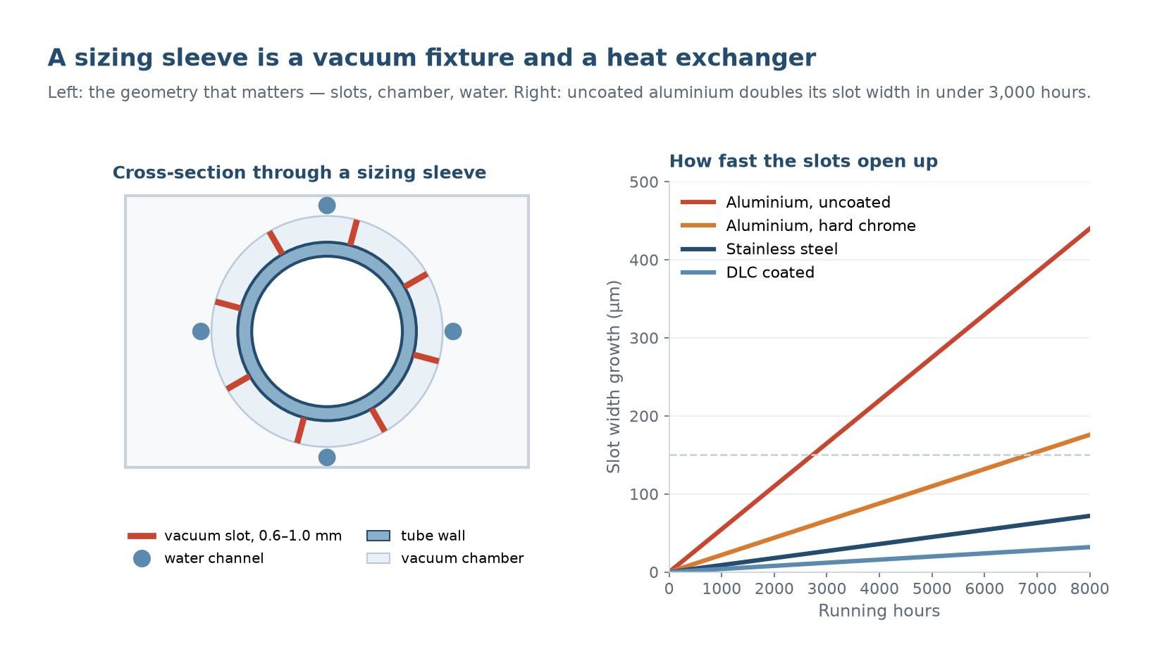
Vacuum is the key feature for hollow profiles. Without it, the walls collapse inward as the profile cools and shrinks. With vacuum applied through slots, the outside is held against the sleeve while the inside is supported by internal air pressure or a mandrel.
Vacuum slots: geometry and layout
| Slot parameter | Typical value | If wrong |
|---|---|---|
| Slot width | 0.5 – 1.5 mm | Too wide: marks on the profile; too narrow: poor vacuum |
| Slot length | 10 – 30 mm | Short slots need more of them |
| Slot spacing | 15 – 40 mm along the flow | Too far apart: profile lifts between slots |
| Slot depth behind | 3 – 5 mm channel | Too shallow: restricts flow |
| Slot position | On flats, not on radii | On radii: marking and poor sealing |
| Entry taper | 5 – 15° over 20 – 40 mm | None: profile tears on entry |
Table 2 — Vacuum slot design. The entry taper is the most commonly omitted feature and the one that causes the most start-up scrap.
Slots on radii are a mistake because the vacuum pulls the profile into the corner and leaves a mark that cannot be polished out, and because the seal is poor there. Put slots on flats and let the radius form naturally.
The channel behind the slots matters as much as the slots. A 3 mm deep channel feeding 40 slots along 300 mm has to carry the total air flow; if it is too small, the slots at the far end see almost no vacuum and the profile lifts there.
Water: cooling and lubrication at once
Wet calibration uses water for two purposes. It cools the profile, and it lubricates the interface between profile and sleeve, which reduces the drag that the puller has to overcome.
| Water condition | Effect |
|---|---|
| Too cold (< 15 °C) | Fast cooling, high stress, possible distortion |
| Moderate (20 – 35 °C) | Balanced; most profiles run here |
| Warm (40 – 55 °C) | Slower cooling, lower stress, better surface |
| Too warm (> 60 °C) | Profile not set before the puller; distortion |
| No flow / stagnant | Local hot spots; the classic cause of one-sided distortion |
Table 3 — Calibration water temperature. The common failure is not the temperature but the flow — a partially blocked channel creates a local hot spot that shows as a flat or a wave.
Water quality matters for scale. Hard water deposits scale in the cooling channels and behind the vacuum slots, and scale insulates. A sleeve that has been in service for a year in hard water may be running at 60% of its original cooling capacity, which shows up as a need to slow the line.
Wear: how it happens and what it looks like
| Wear mode | Cause | Symptom |
|---|---|---|
| Abrasive wear | Filled compounds (talc, glass, wood flour) | Dimensions grow; surface becomes rough |
| Adhesive wear | Sticking, poor lubrication | Scoring, marks along the flow direction |
| Corrosion | PVC (HCl), wet environment, poor water chemistry | Pitting, roughness, marking |
| Erosion at slots | High water velocity through slots | Slots widen; marks get worse |
| Mechanical damage | Handling, cleaning with hard tools | Local dents that print on every part |
Table 4 — Calibrator wear modes. Abrasive wear is the dominant one for filled compounds and it is gradual, which makes it easy to miss.
Abrasive wear is insidious because it is slow and directional. The sleeve gets progressively larger, the profile gets progressively larger with it, and the operator compensates by adjusting the die or the haul-off. By the time someone measures the sleeve, it is 0.15 mm oversize and the whole process has been chasing it for months.
The control is to measure the sleeve on a schedule. A bore gauge or a coordinate measurement on the critical dimensions every three months, recorded, gives a wear trend. When the trend reaches 50% of the tolerance band, order a replacement — not when the parts start failing.
Materials and coatings
| Material / coating | Wear resistance | Cost | Use |
|---|---|---|---|
| Aluminium | Low | Lowest | Short runs, unfilled compounds |
| Anodised aluminium | Medium | Low | General purpose |
| Hard anodised (50 µm) | Good | Medium | Filled compounds, PVC |
| Stainless steel | Good | Medium-high | PVC, corrosive environments |
| Bronze / brass | Medium | Medium | Good thermal conductivity, low friction |
| Hard chrome plating | Very good | High | High-wear, tight tolerance |
| PTFE coating | Low (wears off) | Low | Release only; not a wear solution |
Table 5 — Calibrator materials. Hard anodising is the standard upgrade for filled compounds and it roughly doubles sleeve life for a modest cost.
PTFE coating is often specified to solve a sticking problem and it does help — for a few weeks. It is a release coating, not a wear coating, and once it wears through the sticking returns worse than before. For a genuine sticking problem the fix is water flow, entry taper or surface finish.
Diagnosing from the product
| Symptom | Likely calibrator cause | Check |
|---|---|---|
| Dimensions drifting larger over months | Sleeve wear | Measure the sleeve bore |
| Marks along the flow direction | Scoring, poor lubrication, slot marks | Inspect sleeve surface and water flow |
| One side flat or distorted | Local hot spot from blocked water channel | Water flow at each outlet |
| Profile lifts off between slots | Insufficient vacuum, channel too small | Vacuum level at the far end of the sleeve |
| Tearing at entry | Missing or too-sharp entry taper | Entry geometry; melt temperature |
| Excessive puller load | Drag from poor lubrication or a tight sleeve | Puller amps; water flow |
| Ovality | Uneven vacuum or uneven wall | Slot layout; die concentricity |
Table 6 — Reading product defects for calibrator problems. The one-sided flat is the classic sign of a blocked water channel.
Puller load is an underused diagnostic. A rising puller current over weeks means the profile is dragging more in the calibrator, which means either the sleeve is worn rough or the water flow has dropped. It is a trend that can be logged automatically and it warns you before the product goes out of tolerance.
What is the difference between a die and a calibrator?
The die sets the shape and the wall; the calibrator sets the final outside dimension and cools the profile. The die is the expensive, long-life tool; the calibrator is a wear part that is replaced several times over the die's life.
How often should calibrators be replaced?
Depends on the compound. Unfilled resin might give 3–5 years; a talc-filled or wood-flour compound can wear a sleeve out in 12–18 months. Measure the critical dimensions every three months and replace at 50% of the tolerance band.
Why do I get marks along the profile?
Either the sleeve surface is scored, the vacuum slots are leaving marks, or the water flow is insufficient so the profile is dragging. Check the sleeve surface first, then the water flow, then the slot width — slots wider than 1.5 mm will mark soft compounds.
Can I repair a worn calibrator?
Aluminium sleeves can sometimes be re-machined oversize and used for a looser tolerance product, but they cannot be restored to original size. Coatings can be stripped and re-applied, which is worth it for hard chrome but not for anodising. In practice, replacement is the normal route.
Why does one side of my profile come out flat?
A blocked or slow water channel on that side. The profile cools unevenly, shrinks differently, and the side that cooled slower distorts. Check the water flow at each outlet and clean the channels — hard water scale is the usual cause.
Does the entry taper really matter?
Yes. Without a taper the profile tears or folds as it enters, and the tear becomes a surface defect that runs for the whole production. A 5–15° taper over 20–40 mm is enough and costs almost nothing to machine.
What vacuum level should I use?
Typically −0.3 to −0.7 bar at the sleeve. Higher vacuum holds the profile better but increases drag and wear. Use the lowest level that holds the dimensions, and check the vacuum at the far end of the sleeve — it is always lower than at the inlet.
Can I use one calibrator for several profiles?
Only if the profiles share the same outside geometry in the calibrated section. In practice each profile needs its own sleeve, which is why calibrator cost is part of the per-product tooling quote and not a shared overhead.
Profile dimensions drifting, or marks appearing?
Tell us the profile, the compound, the calibrator age and the defect. We will tell you whether it is wear, water flow or vacuum — and whether a recoated sleeve or a new one is the right call.




 EN
 ES
 FR
 DE
 PT
 AR
 RU
 JA
 KO
 IT
 NL
 TR
 PL
 ID
