
The runner is scrap, and it still has to be right
In a cold runner tool, everything in the runner system is reground or discarded. It is the most obviously wasteful part of the process, and the instinct is to make it as small as possible. That instinct runs straight into the pressure budget.
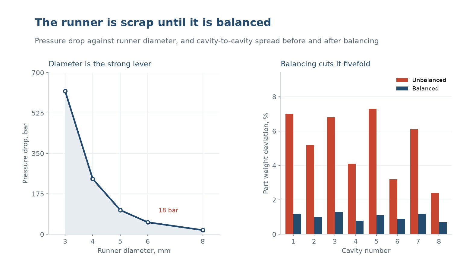
Pressure drop along a runner goes as the inverse of the diameter to the fourth power for a circular channel, so diameter is an extremely strong lever. Going from 3 mm to 4 mm takes the drop from 620 bar to 240; to 5 mm 105; to 6 mm 52; to 8 mm 18.
That is a factor of thirty-four across the range, and it is why runner sizing is not a cosmetic decision. A runner that is one millimetre too small can consume the entire pressure budget of the machine, and a runner that is two millimetres too large wastes material on every shot for the life of the tool.
Balance is about the flow path, not the drawing
A runner is balanced when every cavity sees the same flow length and the same restriction. On an eight-cavity tool with an unbalanced runner, the part weight varies by up to 7.3 percent between cavities, because the cavities further from the sprue see a longer path and a higher pressure drop.
A balanced runner brings that spread to about 1.2 percent, and the effect on the part is larger than the weight difference suggests. A cavity that fills at a different rate has a different orientation, a different shrinkage and a different weld line position, so the parts are not interchangeable even when they look alike.
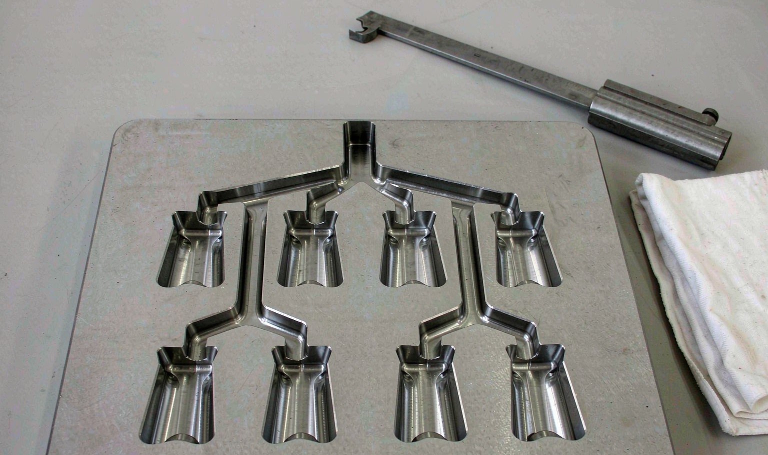
The classic balanced layout is an H pattern, where the runner splits into two equal halves at each level and every cavity is the same distance from the sprue. It costs more runner volume than a straight line and it is the only way to get equal fill without a hot runner or a flow-balancing feature.
Sizing the diameter
The runner has to deliver the melt to the gate at a pressure and a temperature that the gate can use. Start from the pressure budget: what the machine can deliver, minus what the cavity and the gate will consume, leaves what the runner may consume. Then choose the diameter that fits.
There is a second constraint, which is residence time. A runner that is too large holds a lot of melt, and that melt sits in the channel between shots and degrades. A large runner solves a pressure problem and creates a material problem, and the two have to be balanced.
A common practical rule is to size the runner so that its diameter is at least the part wall thickness and at most about twice it, then check the pressure. That rule keeps the runner from freezing before the cavity fills without making it a reservoir.
| Diameter | Pressure drop | Runner volume | Verdict |
|---|---|---|---|
| 3 mm | 620 bar | Lowest | Too restrictive for most parts |
| 4 mm | 240 bar | Baixa | Marginal, thin parts only |
| 5 mm | 105 bar | Moderado | Good general choice |
| 6 mm | 52 bar | Elevado | Large parts, long flow |
| 8 mm | 18 bar | Highest | Residence time risk |
Table 1 — Runner diameter against pressure and volume
Hot runners change the arithmetic
A hot runner keeps the melt at temperature in the manifold, so there is no runner to regrind and no runner pressure drop in the same sense. The cost moves to the tool, to the temperature control and to the maintenance, and the benefit is material and cycle time.
The balancing problem does not disappear. A hot runner manifold has its own flow paths and its own pressure drops, and an unbalanced manifold gives the same cavity-to-cavity variation as an unbalanced cold runner. It is balanced by design, with equal-length paths or with adjustable valve gates.
The other hot runner issue is residence time and degradation. A manifold holds a volume of melt that may sit for many cycles, and a heat-sensitive polymer will degrade there. This is why hot runners are common in polyolefins and rare in PVC.
What an unbalanced runner looks like
The first symptom is dimensional variation between cavities, which is often blamed on the tool dimensions and is actually a fill difference. Measure the part weight by cavity before measuring anything else, because weight is the fastest indicator of fill balance.
The second is a short shot in one cavity only, usually the furthest one. Operators respond by raising the pressure, which over-packs the near cavities and produces flash there. The right fix is the runner, not the pressure.
The third is a difference in weld line position or appearance between cavities, which shows up as a cosmetic reject rate that varies by cavity. A balanced runner makes the cavities behave identically, which is the only way to have one set of process settings.
Getting it right in practice
Design the runner for balance first, then size the diameters for pressure, then check the residence time. Doing it in the other order produces a runner that is hydraulically adequate and geometrically unbalanced, which is the worst of both.
On an existing tool, the fastest diagnostic is a short-shot study: run at a low fill and see which cavities fill first. The order tells you the imbalance directly, and it takes a few shots rather than a simulation.
| Symptom | Likely cause | Fix |
|---|---|---|
| One cavity short | Unbalanced runner | Rebalance or resize |
| Weight varies by cavity | Fill imbalance | Short-shot study |
| Flash on near cavities | Over-pressure to fill far ones | Fix the runner, not the pressure |
| Cosmetic reject varies by cavity | Different weld position | Balance the fill |
| Degraded parts | Runner too large | Reduce diameter |
Table 2 — Diagnosing a runner problem from the symptom
How do I know if my runner is balanced?
Run a short-shot study at a low fill and see which cavities fill first. If they fill together, it is balanced. Weighing parts by cavity is the second check and it is quicker on a running tool.
What is the minimum runner diameter?
At least the part wall thickness, and usually a little more, so that the runner does not freeze before the cavity fills. Below that the pressure drop rises very fast because it goes with the fourth power of diameter.
Is a hot runner always better than a cold runner?
No. It removes runner scrap and can shorten the cycle, and it adds tool cost, temperature control and residence time risk. It is better at high volume and for materials that tolerate it.
Why does one cavity short shot?
Usually an unbalanced runner, so that cavity sees a lower pressure. It can also be a blocked gate or a venting problem, and the short-shot study distinguishes them.
Does runner size affect cycle time?
Yes. A thick runner has to cool before ejection, so a large runner adds cooling time. That is the hidden cost of solving a pressure problem with diameter.
Can an unbalanced runner be fixed without a new tool?
Sometimes, by changing gate sizes to equalise the restriction, or by adding a flow restrictor. Both are compromises and both are better than running with an imbalance.
A multi-cavity tool that will not fill evenly?
Send the runner layout and the cavity weights. We will tell you whether the imbalance is the runner or the gates, and what it takes to fix it without a new plate.
Continue reading
- Gate Design: Type, Size and Position Decide the Whole Part
- Two-Stage Injection Molding: When the Barrel Is the Wrong Tool
- Injection Cycle Time Reduction: Where the Seconds Actually Are
- Cooling Time Optimization: The Part Is Cold When It Leaves
- Custom Injection Molding: Tooling, Tolerances and Volume




 PT
 EN
 ES
 FR
 DE
 AR
 RU
 JA
 KO
 IT
 NL
 TR
 PL
 ID
