
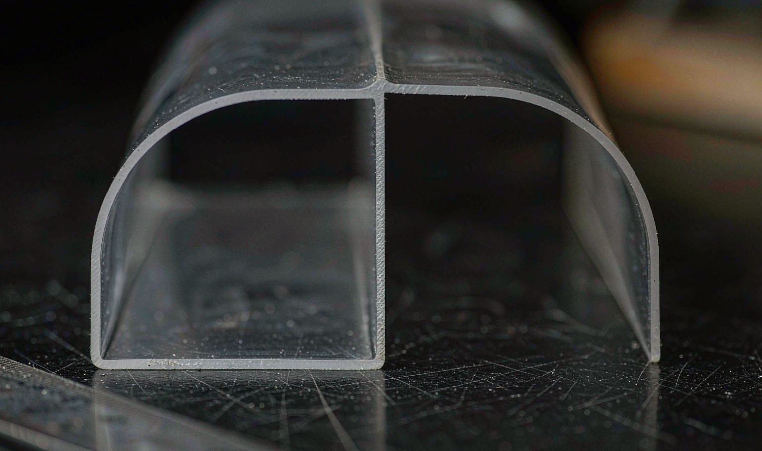
A formed part has three different thicknesses
The single most useful thing to know about vacuum forming is that the finished part is not one thickness. It is at least three, and they are located in predictable places.
The flat panel areas, where the sheet only had to stretch slightly to reach the mold, are the thickest. The corners, where the material has to stretch in two directions at once, are the thinnest. And the draw-down areas between the mold features are somewhere in between, stretched by the pressure difference as the sheet pulls down.
None of this is a defect. It is the geometry of stretching a sheet over a shape. The defect is when the thinnest point falls below the design minimum, which usually happens because the part was designed on the flat pattern thickness without accounting for the stretch.
So the useful question is not how thick is the part. It is how much does the material move, and where.
Draw ratio is the number that predicts it
Draw ratio is the depth of the mold cavity divided by the width of the sheet area that feeds it. A 100 mm deep cavity fed by a 300 mm wide sheet has a draw ratio of 0.33. A 200 mm deep cavity on the same sheet has a draw ratio of 0.67.
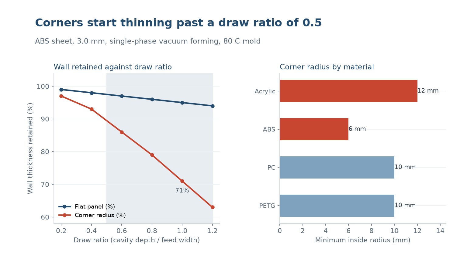
Draw ratio predicts stretch because it is really a measure of how much sheet has to travel. Below roughly 0.5, the sheet reaches the mold bottom by stretching in one direction and the walls come out within about 10 percent of the flat thickness.
Above 0.5 the material starts running out. The sheet must pull in from the edges to feed the deep areas, so the corners thin and the surface can lose contact with the mold. Above 1.0 the material is stretched past the point where most thermoplastics will hold without a plug or a pressure box.
This is why a deep cabinet door and a shallow tray come off the same machine with completely different wall quality, and why deep draws are nearly always plug-assisted.
Why corners thin faster than anything else
In a flat panel, the sheet is stretched in one direction only. At a corner, it is stretched in two directions at the same time. Doubling the number of stretching directions roughly doubles the strain in the material at that point.
For a 90 degree corner with a 25 mm radius, the material has to stretch around the bend, and the outer surface of the bend carries the highest strain of any point on the part. On a 3 mm sheet formed to a 25 mm radius, the outer fibre stretches by several percent more than the panel and thins correspondingly.
Sharp internal corners are worse. A zero radius cannot be formed at all without the material tearing, and practical minimums are set by the material: 6 mm for ABS and polycarbonate, 10 mm for PETG and polycarbonate, 12 mm for acrylic if you want the surface to stay polished.
The counter-intuitive rule is that a generous radius is often thinner than a tight one at the very corner, because the material has somewhere to go. The stress concentration in a sharp corner is what causes visible stress-whitening and cracking, not the absolute minimum wall.
What actually controls the distribution
Draft is the first lever. Every vertical wall in the mold needs at least 3 degrees of draft so the sheet can release without dragging. Above 6 degrees the sheet releases more freely and the surface keeps better contact with the mold.
Mold temperature is the second. A cold mold freezes the material as it touches, so the sheet locks in place and everything beyond that point has to stretch from a frozen state. A mold held at 60 to 80 C lets the material slip and redistribute.
Plug assist is the third, and the most effective for deep draws. A plug pushes the sheet down and outward at the same time as the vacuum pulls, which stops the corners from taking all the strain. Deep draws without a plug are the classic source of torn corners.
Material choice is the fourth. The material stretches differently, and a polymer with a higher elongation at break tolerates the same draw ratio far better than a brittle one. ABS stretches to roughly 40 percent elongation, polycarbonate to about 70, PETG to more than 100.
| Fator | Poor setting | Better setting | Effect on distribution |
|---|---|---|---|
| Draw ratio | Above 1.0 | Below 0.5 | Keeps thickness in the draw |
| Draft angle | Zero | 6 to 10 degrees | Releases the sheet cleanly |
| Temperatura do molde | 20 C ambient | 60 to 80 C | Lets material redistribute |
| Assist | Vacuum only | Plug assisted | Stops corner tearing |
| Corner radius | 2 mm | 8 to 12 mm | Spreads strain |
Table 1 — What controls how material spreads in a formed part.
Designing the mold around the stretch
Start from the thin point, not the flat. Establish the minimum acceptable wall, then work backwards to find the starting sheet thickness that will deliver it at the worst location.
For a 0.6 draw ratio in ABS, the corner will run roughly 25 percent below the panel. So if the design minimum is 2.0 mm, the panel needs to be 2.7 mm, and the sheet has to be 2.7 mm to begin with. That is a 4 mm sheet, not the 3 mm most people would specify.
Add material where it can be added. A rib on the outside of the wall restores stiffness without needing extra sheet in the corner, and a flange at the top of a deep draw gives the material somewhere to pull from.
And if the geometry cannot be changed, the material can. Switching from ABS to a higher elongation polymer, or adding a dry-blend of regrind at a controlled fraction, moves the acceptable draw ratio rather than fighting it.
Measuring and controlling it in production
In production, the practical check is a sectioned part at the corner. Cut one part at the end of each run, measure the panel and the corner with a calliper, and write both numbers on the run sheet.
For any critical part, a simple ultrasonic or laser gauge is faster than destructive sectioning, and it can be used on every part rather than one.
On the mold side, the most valuable instrument is a temperature gauge at the mold surface. A mold that has drifted 15 C cooler on one side will change the distribution on that side, and the parts will tell you why only after the fact.
And the discipline that helps most is treating the corner as a controlled dimension. Put it on the drawing with a minimum wall, put a limit on it, and check it. It is the dimension that fails quietly.
| Wall location | Typical draw ratio 0.4 | Typical draw ratio 0.8 |
|---|---|---|
| Flat panel | 3.0 mm | 3.0 mm |
| Side wall | 2.8 mm | 2.4 mm |
| Corner radius | 2.6 mm | 1.9 mm |
| Deepest draw-down | 2.7 mm | 2.1 mm |
| Minimum at radius | 2.6 mm | 1.9 mm |
Table 2 — Measured wall thickness by location for a 3 mm ABS sheet.
Why is my vacuum formed part thin at the corners?
Because corners stretch in two directions at once while flat panels stretch in one. The material at the corner carries roughly twice the strain, so it ends up thinner there.
What is a good draw ratio for vacuum forming?
Below 0.5 keeps the wall within about 10 percent of the sheet thickness. Between 0.5 and 1.0 you should expect noticeable corner thinning. Above 1.0 almost always needs plug assist.
Does mold temperature change wall thickness?
Yes, significantly. A mold at 60 to 80 C lets the material continue to redistribute after contact, while a cold mold freezes it on contact and forces all the stretch into the draw.
How do I stop corners tearing during a deep draw?
Add plug assist, raise the mold temperature, increase the corner radius to at least 8 to 12 mm, and check the material elongation at break. Four changes together are usually needed for a hard draw.
Is it normal for a vacuum formed part to have different wall thicknesses?
Yes. A formed part always has flat panels, walls and corners at different thicknesses. The defect is only when the thinnest point drops below the design minimum, which is a design and process question rather than a manufacturing one.
Should I measure wall thickness on every part?
Measure the corner on a sectioned part at the start and end of each run, and use a non-destructive gauge if the part is critical. The corner is the dimension that fails quietly and needs to be on the run sheet.
Parts thinning out at the corners?
Send the part geometry, the sheet material and the starting thickness. We will tell you the achievable draw ratio, where the thin point will land, and what has to change.








 PT
 EN
 ES
 FR
 DE
 AR
 RU
 JA
 KO
 IT
 NL
 TR
 PL
 ID
