
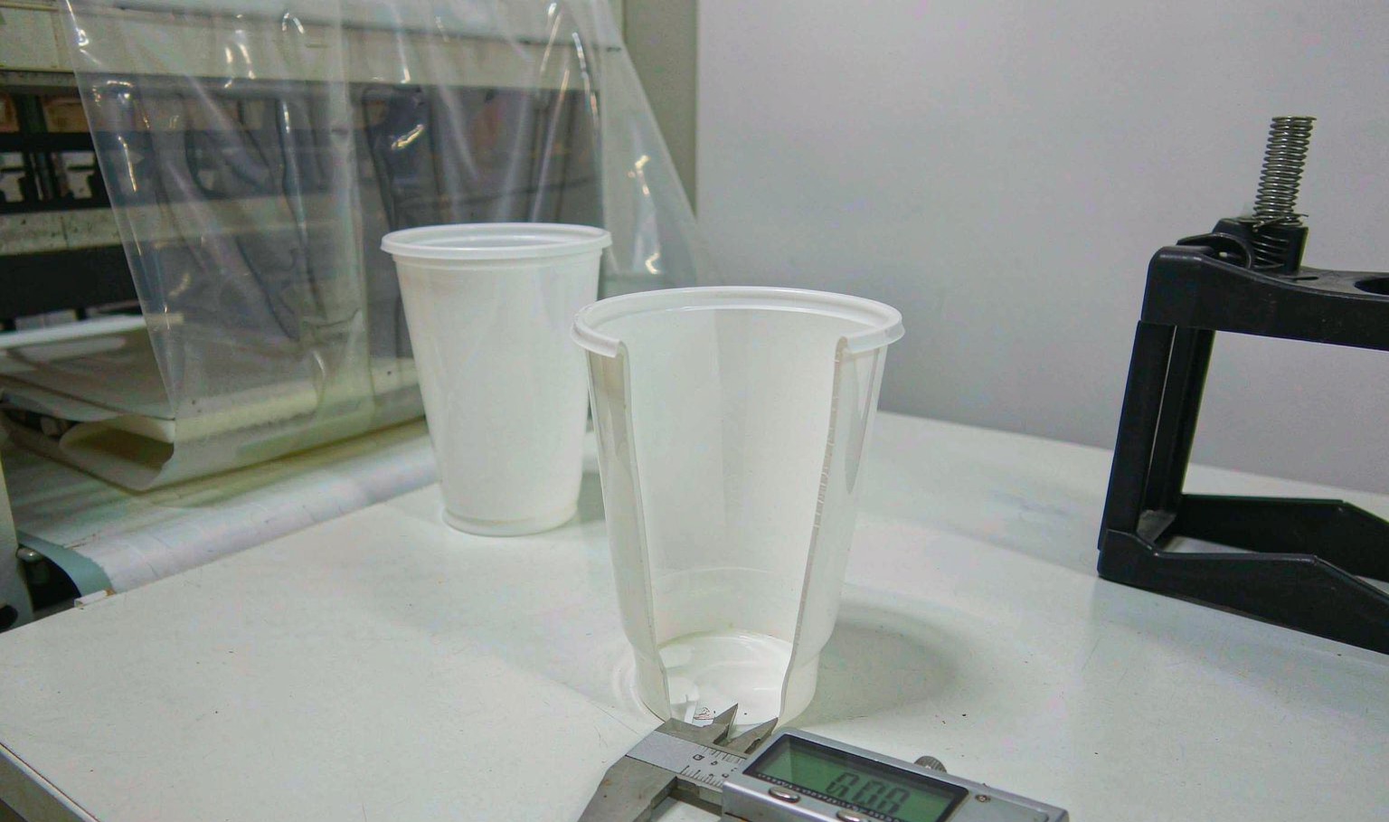
Thinning is predictable
A thermoformed part is made from a flat sheet of uniform thickness, and it ends up with a wall that varies by a factor of three or more. That variation is not random. It follows the geometry, and for a simple shape it can be calculated to within about 10 percent before the tool is cut.
The basis is conservation of material. The sheet has a fixed volume, and forming redistributes it over a larger surface area. Where the surface has stretched most, the wall is thinnest, and the ratio is the local area stretch.
For a simple box or cup, the area stretch at a point is the ratio of the surface area at that point in the formed part to the corresponding area in the flat sheet. Since the flat sheet is uniform, the wall thickness is the original thickness divided by that ratio.
This is why the first thing a former does with a new drawing is estimate the draw ratio. It tells them whether the part is feasible in the specified gauge, and whether the minimum wall will survive the drop test the customer has specified.
The area ratio is the whole calculation
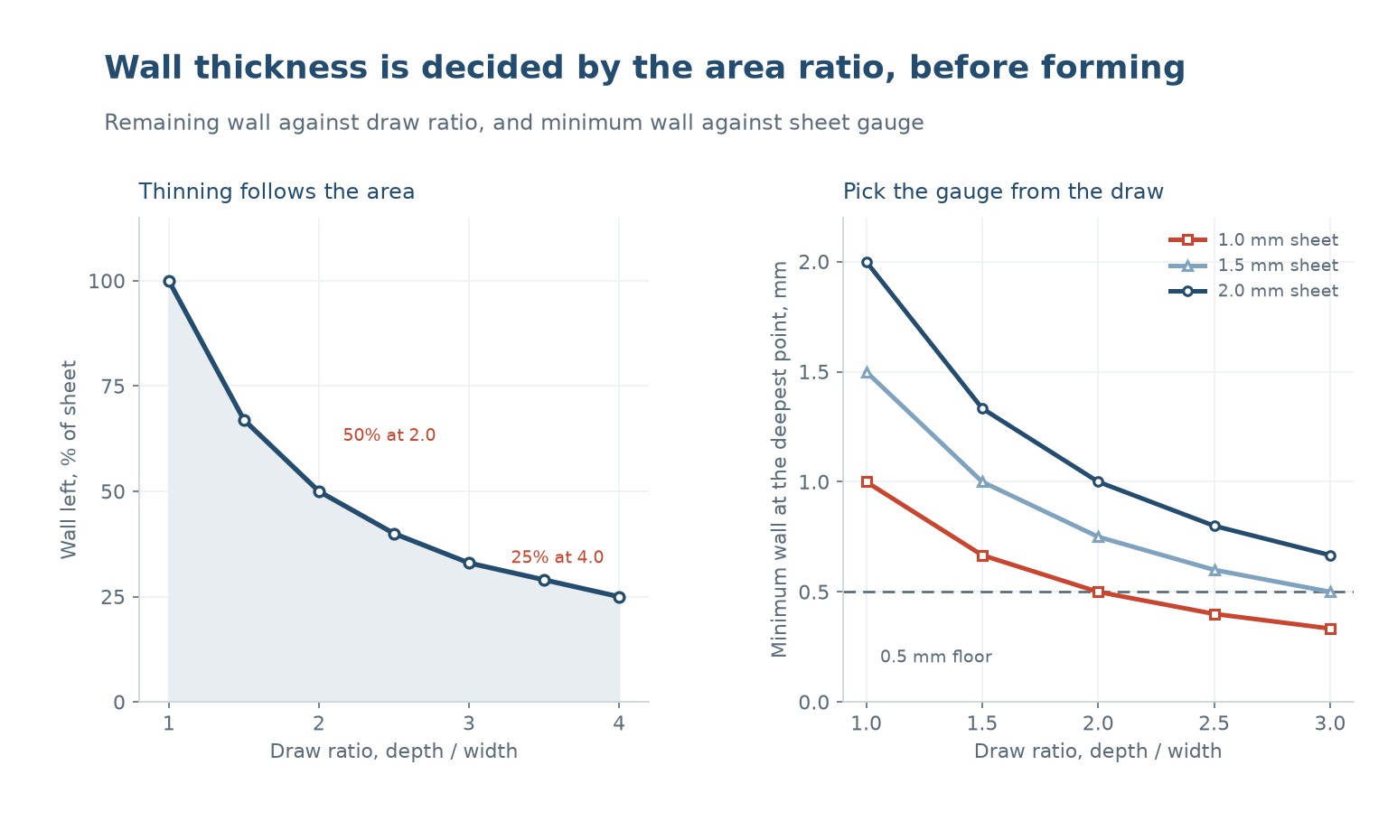
For a simple cylindrical cup formed from a circular blank, the draw ratio is the depth divided by the diameter, and the area stretch at the base is roughly the ratio of the formed surface to the blank area. A cup with a draw ratio of 1 has 100 percent of the sheet thickness at the base, one at 2.0 has 50 percent, at 3.0 about 33 and at 4.0 about 25.
The relationship is close to 1 over the draw ratio for simple shapes, and it is the number to use for a first estimate. Real parts deviate because the corners stretch more than the flats, because the sheet is held at the flange, and because the material does not thin uniformly.
For a rectangular box the calculation is done per region rather than as a single ratio. The corners, where two walls meet, have the highest area stretch and therefore the thinnest wall. The flats are close to the nominal ratio. The base is usually the thinnest point of all, because it takes the full draw.
That is why the minimum wall is almost always at the base corner, and why a part that measures well on the side wall can fail on the base. Measuring in the wrong place is the most common mistake in incoming inspection of formed parts.
Choosing the gauge from the draw
Working backwards from the minimum wall is how the gauge should be chosen. If the deepest point must stay above 0.5 mm, and the local draw ratio there is 2.5, the sheet has to be at least 1.25 mm. Add a margin for the corners and 1.5 mm is the sensible order.
The lines on the right-hand chart show why a single gauge cannot serve a product range. A 1.0 mm sheet falls below 0.5 mm at a draw ratio of 2.0; a 1.5 mm sheet holds until 3.0; a 2.0 mm sheet holds to 4.0. If the range includes a deep part and a shallow one, either the gauge changes or the deep part uses a different forming method.
There is a cost to over-specifying. Going from 1.2 to 1.5 mm adds 25 percent to the material cost of every part, and it adds cycle time because the thicker sheet takes longer to heat and longer to cool. It also reduces the draw ratio that the same shape produces, which can make a marginal part easier or a shallow part over-thick.
The right answer is usually to specify the gauge from the deepest part in the family and accept that the shallow parts are heavier than they need to be, or to split the family into two gauges. Splitting is cheaper than it sounds, because the material saving on the shallow parts pays for the extra sheet item within a season.
| Draw ratio | Wall left | 1.0 mm sheet | 1.5 mm sheet | 2.0 mm sheet |
|---|---|---|---|---|
| 1.0 | 100% | 1.00 mm | 1.50 mm | 2.00 mm |
| 1.5 | 67% | 0.67 mm | 1.00 mm | 1.33 mm |
| 2.0 | 50% | 0.50 mm | 0.75 mm | 1.00 mm |
| 2.5 | 40% | 0.40 mm | 0.60 mm | 0.80 mm |
| 3.0 | 33% | 0.33 mm | 0.50 mm | 0.67 mm |
Table 1 — Minimum wall at the deepest point for three gauges
Plug assist changes the profile, not the average
A plug assist pushes material into the cavity before the vacuum comes on, and it changes where the thinning happens. The plug mechanically stretches the sheet, so the material under the plug thins first and the material at the flange is drawn in later. The average wall is the same; the distribution is different.
That is the point. A part that would be 0.3 mm at the base and 1.0 mm at the rim without a plug can be 0.5 mm at the base and 0.7 at the rim with one. The minimum goes up, which is what the drop test cares about, even though the material is the same.
The plug shape matters. A plug that matches the cavity shape pre-stretches evenly; a plug that is too small concentrates the stretch under its edge and produces a ring of thin wall. A plug that is too large traps material and causes a fold.
The plug temperature matters as well. A cold plug grabs the sheet and stretches it locally; a warm plug lets it slide and stretches a larger area. For deep draws, a plug at 80 to 120 C gives a more uniform result than a cold one.
| Metoda | Draw ratio | Wall uniformity | When to use |
|---|---|---|---|
| Straight vacuum | up to 1.5 | Poor at the base | Shallow trays and lids |
| Vacuum with plug | up to 2.5 | Dobry | Cups, boxes, general parts |
| Pressure forming | up to 3.0 | Dobry | Thin-wall food containers |
| Pressure with plug | up to 3.5 | Best | Deep technical parts |
| Twin sheet | n/a | Controlled by design | Hollow parts and ducts |
Table 2 — Forming method against achievable draw
Measuring on a formed part
The measurement that matters is the minimum wall, and it is found by sectioning the part through the deepest corner and measuring with a ball-anvil or a pointed-blade micrometer. A flat-anvil micrometer on a curved wall reads the chord, not the thickness, and it reads high.
A quick non-destructive check is ultrasonic, but it needs a couplant and a calibration on the same material, and on a thin formed wall the reading is sensitive to the probe angle. It is useful for a trend, not for a specification.
The inspection plan should specify where to measure: the base centre, the base corner, the side wall mid-height and the rim. Four points on a sectioned part tell the whole story, and they catch the corner thinning that a single base measurement misses.
For production control, weighing the part is faster and more robust than measuring it. If the part weight is stable and the sheet gauge is known, the average wall is stable. The minimum wall can then be checked on a sample per shift rather than every part.
When the wall comes out wrong
If the part is uniformly thin, the sheet gauge is wrong or the sheet is being over-stretched by a forming problem. Check the gauge first, then the draw ratio, then the temperature.
If one area is thin and the rest is fine, it is a local draw problem: a tight corner, a deep rib, or a plug that is too small. The fix is geometric, in the tool, not in the process.
If the wall varies around the part, the sheet is probably uneven or the heating is uneven. A gauge profile across the sheet and a thermal image of the heated sheet will show which. Zone heating is the usual fix for the second.
If the wall is thick everywhere, the draw ratio is lower than designed, which usually means the part is being formed shallower than the tool or the sheet is not being drawn fully into the corners. Check the vacuum and the venting before touching the gauge.
How do I calculate wall thickness in a thermoformed part?
Divide the sheet thickness by the local area stretch. For a simple shape the area stretch is close to the draw ratio, so a draw ratio of 2 leaves half the sheet thickness.
Where is a thermoformed part thinnest?
At the base corner, where the draw is deepest and two walls meet. The base centre and the side wall are usually thicker.
What draw ratio can I form?
About 2.5 with vacuum and 3.5 with pressure forming or a plug assist, depending on the material and the sheet gauge.
How do I choose the sheet gauge?
From the minimum wall you need at the deepest point: gauge equals minimum wall times the local draw ratio, plus a margin for the corners.
Does a plug assist make the wall thicker?
No, it makes it more uniform. The average is unchanged, but the minimum at the base rises and the rim thins, which is usually what is wanted.
Why is my part thin on one side only?
Uneven sheet gauge or uneven heating. Check the gauge profile across the sheet and the temperature profile across the heater.
A part that is too thin at the base?
Send the drawing with the depth and the required minimum wall. We will calculate the draw ratio and tell you the gauge and the forming method that will hold it.




 PL
 EN
 ES
 FR
 DE
 PT
 AR
 RU
 JA
 KO
 IT
 NL
 TR
 ID
