
Pressure at the tool, not at the compressor
A pressure forming machine is specified by the pressure it can deliver at the tool, and a compressor is specified by the pressure it can hold in a receiver. Between the two there is pipework, a filter, a regulator, a valve and often twenty metres of hose, and each of them costs pressure. A system showing 7 bar on the compressor gauge can deliver 4.5 bar at the tool, which is at the bottom of the usable range.
The loss is not linear and it is not obvious. A regulator drops a fixed amount by design. A filter drops more as it loads, which means the pressure at the tool falls slowly over weeks and nobody connects the change to the filter. A hose one size too small drops pressure in proportion to the square of the flow, so a short forming pulse at high flow loses far more than a steady draw of the same average.
The measurement that settles it is a gauge at the tool, or better a pressure logger on the forming line for a shift. The difference between the compressor gauge and the tool gauge is the number to fix, and fixing it is usually cheaper than a bigger compressor.
The second measurement is flow. A pressure former consumes air in bursts: almost nothing for most of the cycle, then several hundred litres in half a second. Sizing the supply on average consumption produces a machine that cannot hold pressure during the burst, because the compressor cannot respond in that time and the receiver has to.
Detail stops improving at about four bar
The chart on the left plots detail replication against forming pressure for a textured part. At 1 bar it is 22 percent, at 2 bar 44, at 3 bar 68, at 4 bar 86, at 5 bar 93, at 6 bar 96 and at 8 bar 97. The shaded band from 4 bar upward is the range in which the machine is doing what it was bought for.
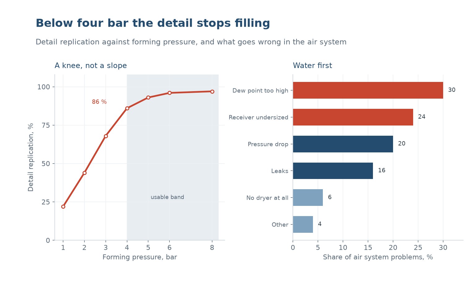
The curve has a knee rather than a slope, and the knee is where the sheet has fully conformed to the tool. Below it, more pressure presses the sheet further into texture and into corners. Above it, the sheet is already touching everywhere and more pressure changes nothing except the stress locked into the part.
That is why 4 to 6 bar is the practical range and why a machine rated at 8 bar is not twice as capable as one rated at 4. The extra pressure is useful for thick sheet and deep draws, where the force needed to stretch the material is genuinely higher, and it is wasted on a thin textured part.
The corollary is that a machine which cannot reach 4 bar at the tool is losing detail it was designed to produce, and the fix is almost always in the supply rather than in the machine. Before buying a higher rated machine, measure the pressure at the tool during a forming pulse.
Dew point causes more defects than pressure
The right hand panel shows where air system problems come from: dew point too high 30 percent, receiver undersized 24, pressure drop 20, leaks 16, no dryer at all 6. Dew point is the largest and it is the one that shows up as a defect rather than as a pressure problem, which is why it is often misdiagnosed for months.
Compressed air at 7 bar and 25 degrees Celsius holds far more water vapour than the same volume at atmospheric pressure. When the air expands through the forming valve it cools, and the water condenses. On a pressure box the condensate lands on the sheet as fine droplets, and on the tool it accumulates in the texture and in the vacuum holes.
The defects it produces are specific. Water marks on the formed surface, a dull patch where the condensate sat, and small dimples where a droplet was trapped between sheet and tool. On a clear part the same water shows as a haze. None of these respond to more pressure or to a longer cooling time.
The fix is a refrigerated dryer sized for the peak flow rather than the average, with a dew point of 3 to 7 degrees Celsius, and a coalescing filter after it. A dryer sized on average flow will pass wet air during the forming burst, which is exactly when the water does its damage.
Sizing the receiver for a burst
The receiver exists to cover the difference between what the machine draws in a burst and what the compressor can deliver continuously. The calculation is not complicated, and it is worth doing because an undersized receiver is the second largest cause on the list at 24 percent.
A forming pulse that draws 400 litres at 6 bar in 0.8 seconds is a flow of 500 litres per second, or 30 cubic metres per minute, against a compressor that may deliver 1.5. The receiver has to supply the difference without letting the pressure fall below the minimum the process needs. A useful rule is that the stored volume should cover the pulse with a pressure drop of no more than 0.5 bar.
The practical version is to place the receiver as close to the machine as the layout allows, with a line large enough that the pressure drop along it is negligible at peak flow. A receiver in the compressor room and a 25 mm line across the building does not solve the problem it was installed for.
| Machine size | Peak draw per pulse | Receiver volume | Feed line |
|---|---|---|---|
| Small former, sheet under 1 mm | 150 to 250 litres | 300 litres | 20 mm |
| Medium former, 1 to 2 mm sheet | 300 to 500 litres | 500 to 750 litres | 25 mm |
| Large former, sheet above 2 mm | 600 to 1 200 litres | 1 000 to 2 000 litres | 40 mm |
| Twin-sheet machine | 1 000 to 2 000 litres | 2 000 litres or a dedicated compressor | 50 mm |
Table 1 — Indicative receiver volume against peak draw, for a pulse of about one second.
What to measure and what to fix
Four measurements cover almost every case: pressure at the compressor, pressure at the tool during a pulse, dew point at the machine, and the pressure decay rate with the machine idle. The first two give the pressure drop, the third gives the water risk, and the fourth gives the leak load.
A pressure decay test is the cheapest diagnostic in the building. Close the machine valve, charge the line to 6 bar, and watch the gauge for ten minutes with nothing running. A fall of more than 0.2 bar points to leaks that are costing both pressure and money, and the leaks are usually at quick couplings and at the filter bowl rather than in the pipework.
The order of correction follows the numbers. Leaks and filter restriction first, because they are cheap. Then dryer capacity, because it prevents a defect class. Then receiver volume, because it is capital. Then a larger compressor, which is the most expensive answer and is rarely the one that was needed.
| Symptom | Measurement | Likely fix |
|---|---|---|
| Poor detail on a textured part | Tool pressure during pulse below 4 bar | Remove restriction, upsize line or receiver |
| Water marks and dull patches | Dew point above 10 Celsius at the machine | Dryer capacity, coalescing filter |
| Pressure falls during the pulse | Drop over 0.5 bar at the tool | Larger receiver closer to the machine |
| Pressure falls over weeks | Filter differential rising | Replace the element |
| Compressor runs continuously | Decay test with the machine idle | Find and fix the leaks |
Table 2 — Matching the symptom to the measurement and the correction.
A checklist before the next tool
Before a new tool goes on the machine, confirm the pressure the tool needs and the pressure the machine can deliver at that moment. A deep draw in thick sheet needs more than a shallow textured part, and the number should come from the tool design rather than from the last job.
Then confirm the air is dry. A new dryer or a new filter element is a small cost against a batch of parts rejected for water marks, and the defect is easy to attribute to the tool if nobody measures dew point. Put a dew point meter on the line for a week when a new tool is commissioned.
Finally, write the numbers down. The pressure at the tool, the dew point, the receiver volume and the pulse duration are the four values that turn a forming problem from an argument into a diagnosis. A shop that records them once can compare against them for years.
None of this is specific to pressure forming. Vacuum forming with a pressure assist uses the same air, and the same water condenses in the same places. The difference is only that a vacuum former has less pressure to lose, so the defect shows up sooner.
How much air pressure does pressure forming need?
Four to six bar at the tool for most work. Detail replication reaches 86 percent at 4 bar and only 96 percent at 6, so the extra pressure buys little on a textured part and matters mainly for thick sheet and deep draws.
Why does my pressure former show 7 bar but form poorly?
Because the 7 bar is at the compressor. Regulator drop, a loaded filter and an undersized hose can cost 2 bar or more before the air reaches the tool. Measure at the tool during a forming pulse, not at the compressor.
What causes water marks on pressure formed parts?
Condensation. Air at 7 bar holds far more moisture than air at atmospheric pressure, and it cools as it expands through the forming valve. A refrigerated dryer at 3 to 7 degrees dew point plus a coalescing filter is the fix.
How big should the air receiver be?
Large enough to cover one forming pulse with no more than 0.5 bar of pressure drop. A medium former drawing 300 to 500 litres per pulse typically needs 500 to 750 litres of storage, placed close to the machine rather than in the compressor room.
Is a bigger compressor the answer to low forming pressure?
Rarely. Leaks, a restricted filter, an undersized feed line and a receiver that is too small all cost pressure at the tool and all cost less to fix than a compressor. Do the decay test and the tool pressure measurement first.
Does a vacuum former need a dryer too?
Yes, and for the same reason. Water condenses in the vacuum lines and in the tool, blocks vacuum holes and marks the sheet. The defect appears at lower pressure than on a pressure former, so it is often blamed on the tool.
A forming station that holds its pressure
Tell us the sheet, the draw depth and the texture you need to reproduce. We will tell you what pressure the tool has to see, and what the air system behind it has to deliver to keep it there.




 PL
 EN
 ES
 FR
 DE
 PT
 AR
 RU
 JA
 KO
 IT
 NL
 TR
 ID
