
Three ways a pin leaves a mark
An ejector pin mark is a local depression, a stress whitening or a small raised witness around the pin. All three come from the same place: the pin has to transfer enough force to break the grip the part has on the core, and it does it through a small area.
The first mechanism is punching. If the part is still soft, the pin pushes into it rather than pushing it off, and the mark is a shallow dish the depth of the pin travel. The second is yielding. If the part is hard and the grip is high, the pin has to push hard enough that the local stress exceeds the material's yield strength, and the mark is a permanent dimple with a white halo. The third is witness. Even a clean ejection leaves a faint circle where the pin met the surface, and on a textured or high-gloss part that circle is visible.
Only the third is unavoidable in principle, and it is a matter of pin placement and surface matching rather than force. The first two are process and design problems, and they are the ones that produce scrap.
| Mechanism | Aspetto | Root cause | Fix |
|---|---|---|---|
| Punching | Shallow dish, pin-shaped | Ejected while still soft | Eject later, more cooling |
| Yielding | Dimple with white halo | Force over a small pin area | Bigger pins, more of them |
| Witness | Faint circle, no depth | Pin face against a textured surface | Match the pin finish, or hide it |
| Stress whitening | Chalky patch around the pin | Local overstress at ejection | Draft, polish, ejector speed |
Table 1 — The four marks an ejector pin can leave, and what causes each.
There is a window, not a direction
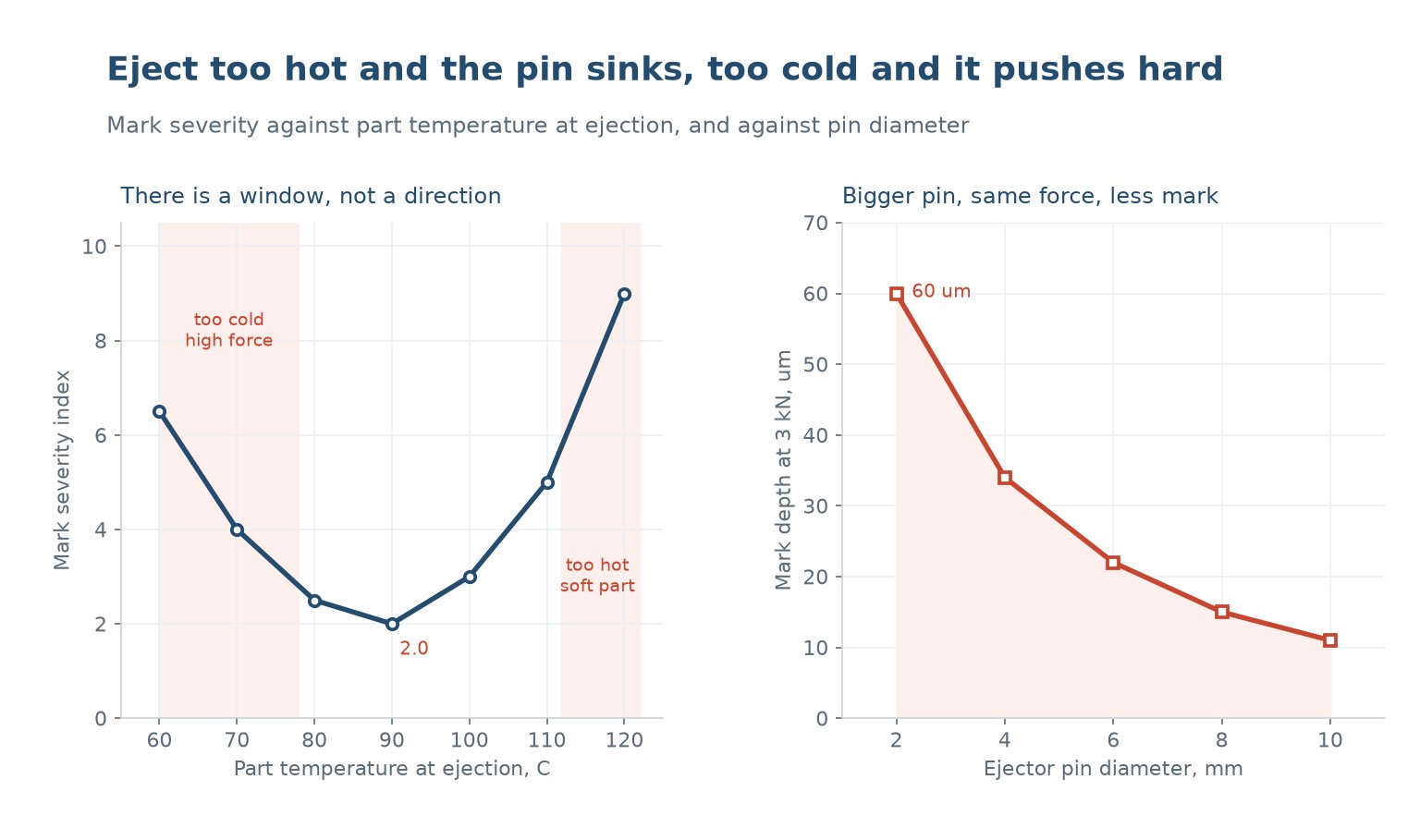
The intuitive fix is to eject later, so the part is cooler and stiffer. That helps up to a point and then makes things worse, because a cooler part has shrunk further onto the core and grips harder. The severity curve is a U, with a minimum in the middle.
On a 2 mm ABS part with a 40 mm core, the mark severity index runs 6.5 at 60 C, 4.0 at 70, 2.5 at 80, 2.0 at 90, 3.0 at 100, 5.0 at 110 and 9.0 at 120. The bottom of the U is around 85 to 95 C, which is 30 to 40 C below the material's heat deflection temperature.
On the hot side the part is soft and the pin punches. On the cold side the shrink has closed onto the core, the ejection force has risen, and the pin has to push hard enough to yield the surface. The two failure modes meet in the middle, and that meeting point is where the process should run.
This is why adjusting cooling time alone so often fails to fix a pin mark. If the mark is a punch, more cooling helps; if it is a yield dimple, more cooling makes it worse. The first step is always to identify which side of the U the process is on, and the way to do that is to run the cooling time up and down and watch whether the mark improves or degrades.
Pin area is the second lever
Contact stress is force divided by area, and the area of a round pin goes with the square of its diameter. Doubling the diameter quarters the stress, which is why pin sizing has more effect than most process changes.
At a total ejection force of 3 kN spread over a single pin, a 2 mm pin sees 955 MPa, a 4 mm pin 239 MPa, a 6 mm pin 106 MPa, an 8 mm pin 60 MPa and a 10 mm pin 38 MPa. Since the yield strength of ABS is around 45 MPa, only the 8 and 10 mm pins stay below it.
In practice the force is shared between several pins, so each one carries less. But the ratio is what matters: a part ejected on four 4 mm pins has the same total area as one 8 mm pin, and the same average stress. What differs is the distribution, and a part that is stiff in the middle and flexible at the edges will load the pins unevenly, with one taking twice its share.
| Pin diameter | Area | Stress at 3 kN | Mark depth |
|---|---|---|---|
| 2 mm | 3.1 mm2 | 955 MPa | 60 um |
| 4 mm | 12.6 mm2 | 239 MPa | 34 um |
| 6 mm | 28.3 mm2 | 106 MPa | 22 um |
| 8 mm | 50.3 mm2 | 60 MPa | 15 um |
| 10 mm | 78.5 mm2 | 38 MPa | 11 um |
Table 2 — Contact stress and measured mark depth for a single pin carrying 3 kN.
Draft and polish decide the force
The force the pin has to overcome is mostly friction between the part and the core, and that friction is set by the shrink, the surface finish and the draft. A core polished to a mirror finish releases at a fraction of the force of a sandblasted one, and 1 degree of extra draft can halve the ejection force on a deep part.
This is why a pin mark often appears on one face of a part and not another. The core side with the texture grips, and the smooth side releases. If the texture is only cosmetic, moving it to the cavity side or reducing its depth is a cheaper fix than adding pins.
The material matters as well. An unmodified polystyrene shrinks hard onto a core and grips; a high-impact grade with rubber particles releases more easily but marks more readily because its surface yields at a lower stress. There is no free choice here, and it is worth testing a pin layout on the actual grade rather than on a generic one.
Setting ejection in the machine
Ejection has three settings that matter: the speed of the ejector plate, the force or pressure limit on the ejector, and the point in the cycle where it starts. Most machines run the ejector too fast by default, because fast ejection looks efficient and the plate returns sooner.
A slow first stage that breaks the grip, followed by a faster second stage that clears the part, removes most punch marks without adding cycle time. The slow stage only has to travel a millimetre or two. The same two-stage approach that fixes jetting in injection fixes pin marks in ejection, for the same reason: the first moments set the outcome.
The force limit is the safety net. If the ejector is pressure-limited rather than position-limited, a part that is gripping hard will stall instead of being punched, and the operator sees a fault rather than a box of scrap. Setting the limit just above the normal ejection force is good practice on any part with a cosmetic surface.
What to change on the tool
When the process window is exhausted, the tool has to change, and the order of preference is: more draft, then more pin area, then pin placement.
- Add 1 degree of draft on the core walls, which reduces the grip more than any other single change.
- Polish the core to a SPI B-1 or better, or move the texture to the cavity side.
- Increase the pin diameter, or replace one large pin with several smaller ones spread over a stiff area.
- Move pins away from thin walls and corners, where the part is least able to take the load.
- Match the pin face finish to the surrounding surface, or recess the pin 0.05 mm so the witness becomes a deliberate feature.
The last item is worth doing on any visible part. A pin that sits 0.05 mm below the surface leaves a shallow, even recess that reads as a moulded detail, where a pin flush with a textured surface leaves a bright ring that reads as a defect.
Why do ejector pin marks appear even with a long cooling time?
Because the severity curve is a U. Past the minimum, around 85 to 95 C on ABS, a cooler part has shrunk further onto the core and grips harder, so the pin has to push harder and the mark gets worse.
What is the best ejector pin size?
As large as the part allows. Contact stress goes with the square of the diameter, so a 10 mm pin sees 38 MPa where a 2 mm pin sees 955 MPa at the same 3 kN.
Does more draft help ejector pin marks?
Yes, more than any other tool change. An extra degree of draft can halve the ejection force on a deep part, which removes the mark without adding pins.
What causes a white halo around an ejector pin?
Local yielding. The stress at the pin exceeds the material's yield strength, and the polymer whitens as it deforms. The fix is more pin area or lower ejection force.
Can ejector pin marks be polished out?
Only the witness ring. A punched dish or a yield dimple has deformed the surface permanently, and polishing removes material without restoring the flatness.
Should the ejector be pressure limited?
On cosmetic parts, yes. A pressure limit lets the machine stall and alarm instead of punching the part, so a gripping part becomes a fault rather than a box of scrap.
Fighting pin marks on a visible part?
Send the part drawing with the pin layout and the ejection temperature. We will tell you which side of the curve you are on and whether the fix is the process or the tool.




 IT
 EN
 ES
 FR
 DE
 PT
 AR
 RU
 JA
 KO
 NL
 TR
 PL
 ID
