
What a conductive sheet actually is
A conductive thermoplastic sheet is an ordinary polymer with enough conductive filler in it that the filler particles touch each other. The polymer provides the formability and the chemical resistance; the filler provides a path for charge. There is no alloying and no coating. The sheet conducts because there is a continuous network of carbon or metal particles running through it.
Three families of filler are used. Carbon black is the cheapest and by far the most common, and it is what almost every dissipative tray in the world is made from. Carbon fibre gives lower resistivity at lower loading but it costs more and it shows as a visible texture. Metal fillers, nickel-coated graphite or silver, are used where the requirement is shielding rather than dissipation, and they cost enough that they are specified in grams rather than tonnes.
The property that is specified is almost always surface resistivity, in ohms per square. The industry convention splits it into three bands, and the band a part has to sit in decides everything else about the project.
| Band | Surface resistivity, ohm/sq | What it is for | Typical filler loading |
|---|---|---|---|
| Insulative | above 1e12 | Ordinary plastics; static will build and will not drain | None |
| Static dissipative | 1e6 to 1e9 | Electronics handling; drains charge slowly and safely | 6 to 9 percent carbon black |
| Conductive | 1e2 to 1e6 | Grounding paths, paint lines, explosive atmospheres | 10 to 15 percent carbon black |
| EMI shielding | below 1e2 | Enclosures that have to attenuate a field, not just drain it | Carbon fibre, or nickel-coated graphite |
Table 1 — The four bands, and the loading that gets you into each one.
The distinction between dissipative and conductive matters commercially. A dissipative tray is a commodity item made from a standard carbon-black compound. A shielding enclosure is a specialty part with a metal-filled compound and a test method attached, and the price difference between the two is not small.
Percolation, and why eight percent matters
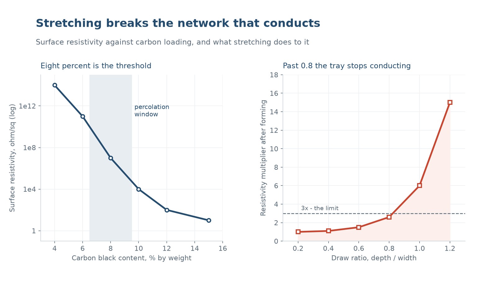
Resistivity does not fall linearly with filler content. It falls off a cliff. At 4 percent carbon black the sheet is still an insulator at 10^14 ohms per square. At 6 percent it is 10^11. At 8 percent it is 10^7. By 12 percent it is 10^2 and by 15 percent it is 10, which is close to the resistivity of the carbon itself.
That cliff is the percolation threshold. Below it, the particles are isolated islands in a polymer sea and charge cannot cross. Above it, there is at least one continuous path from one side to the other, and once there is one path there are usually thousands, so adding more filler barely changes the resistivity.
For thermoforming, the important consequence is that the useful part of the curve is the steep part. A compound at 8 percent sits right on the knee, where a small change in loading moves the resistivity by three or four orders of magnitude. That sounds like a problem and it is also the opportunity: it means the sheet supplier can hit a target band precisely with a small loading adjustment, and it means the processor has to buy from a supplier who controls loading tightly.
Stretching is the enemy
Thermoforming works by stretching a sheet. Conduction works because the filler particles are close enough to touch. Those two facts are in direct conflict, and the conflict is the entire engineering problem of conductive thermoforming.
As the sheet is drawn, the polymer chains orient and the sheet thins. The filler particles go with the polymer, and the distances between them increase in the draw direction while the network is compressed in the other two. The result is that the resistivity rises, and it rises slowly at first and then very fast. At a draw ratio of 0.4 the multiplier is around 1.1; at 0.6 it is 1.5; at 0.8 it is 2.6; at 1.0 it is 6; at 1.2 it is 15.
Put that together with the specification and the design constraint appears immediately. A tray specified at 10^6 ohms per square, made from a sheet that starts at 10^5.5, has a multiplier budget of about 3. That budget is exhausted at a draw ratio of roughly 0.8. Anything deeper, and the deepest corner of the tray is out of specification even though the flat blank tested perfectly.
| Draw ratio, depth / width | Resistivity multiplier | Effect on a 10^5 ohm/sq sheet | Verdict |
|---|---|---|---|
| 0.2 | 1.0 | 10^5 | No measurable change |
| 0.4 | 1.1 | 10^5.04 | Comfortable |
| 0.6 | 1.5 | 10^5.18 | Comfortable |
| 0.8 | 2.6 | 10^5.4 | At the edge of a 3x budget |
| 1.0 | 6.0 | 10^5.8 | Out of specification for most dissipative grades |
| 1.2 | 15 | 10^6.2 | Conductive parts become dissipative; dissipative parts become insulative |
Table 2 — Draw ratio against resistivity multiplier, and what it does to a real specification.
Two things follow. First, a conductive part should be designed shallow, and if it has to be deep it should be formed from a sheet with resistivity well below the target so that the stretched corners land inside the band. Second, the specification should be written on the formed part, at the deepest point, not on the flat sheet. A specification written on the flat sheet is a specification that will be met and a part that will fail.
Draw ratio limits in practice
The number that matters at the drawing board is the ratio of depth to the smaller of the two plan dimensions. A tray 300 by 200 by 60 deep has a draw ratio of 0.3 and will form without any resistivity problem. The same tray at 150 deep has a draw ratio of 0.75 and is at the limit. At 200 deep it is a different project.
Corner radii matter as much as depth, because the corner is where the local draw ratio is highest. A tray with sharp corners has a local draw ratio at the corner that can be twice the nominal one, and that corner is where the resistivity will be highest and where a continuity test will fail. Generous radii are not a cosmetic preference on a conductive part, they are a functional requirement.
- Keep the nominal draw ratio below 0.6 for a dissipative part and below 0.45 for a shielding part.
- Use a corner radius of at least one wall thickness, and preferably two, to keep the local draw ratio near the nominal one.
- Avoid plug assist that stretches locally. A plug pushes material before the vacuum takes it, and the area under the plug is drawn hardest.
- Form hot. A hotter sheet has lower resistance to stretching, so the thickness distribution is more even and the peak local draw ratio is lower.
- Do not re-form or re-strike a part that is out of tolerance. The second draw adds to the first.
There is also a lower limit, which is less obvious. A part that is formed very shallow, at a draw ratio below 0.15, can show a resistivity that is slightly lower than the flat sheet, because the slight orientation improves the contact between filler particles in the plane. It is a small effect and it is not worth designing around, but it explains occasional readings that look impossible.
Heating a sheet that conducts
A carbon-loaded sheet is black, and a black sheet absorbs infrared radiation very efficiently. On a radiant heater set for a natural sheet, a conductive sheet will reach forming temperature in perhaps 60 percent of the time, and it will keep climbing if the cycle is not shortened. The first symptom is sag, the second is a part that is glossy on the outside and blistered inside.
The fix is to reduce the heater output rather than the time, because the time is what sets the through-thickness gradient and you want to keep that. Lower the heater percentage until the sheet reaches the same surface temperature in the same time as the natural grade, then check the core temperature with a needle probe. A black sheet that is surface-hot and core-cold will form a part with high residual stress and a resistivity that drifts over the following week.
There is a second effect that catches people out. The sheet conducts, so heat spreads laterally through the carbon network as well as through the polymer. The practical consequence is that the sheet reaches a more uniform temperature across its area than a natural sheet does, which is helpful, but the edges lose heat to the frame faster because the network carries heat to them. Edge scrap on a conductive sheet is often 20 to 30 mm rather than the 10 to 15 mm you would allow on the same part in ABS.
Surface against volume resistivity
The number in the specification is usually surface resistivity, measured with a concentric ring probe on a flat specimen. What actually protects the electronics is the resistance from any point on the part to the ground point, which is a volume and contact property, and the two are related but not interchangeable.
Surface resistivity is easy to measure and easy to specify, and it is dominated by the surface layer. A moulded part can have a resin-rich skin from contact with a hot tool, and that skin can be several times more resistive than the core, so a part that measures well on the flat sheet measures badly on the formed face. Volume resistivity, measured through the thickness with a guarded electrode, is the more honest number, but it is harder to specify and harder to check.
For most projects the practical resolution is to specify surface resistivity because that is what the supply chain understands, and to test it on the formed part at the point of maximum draw. If the part is a shielding enclosure, specify shielding effectiveness as a system property and let the compound choice follow from that, because no resistivity number maps cleanly onto an attenuation figure.
Testing what you shipped, not what you bought
The test that matters is on the finished part. Take the deepest corner, the corner with the tightest radius, and the flat area, and measure all three with the same probe at the same humidity. If the deepest corner is out of band, the part is out of band, whatever the certificate on the sheet says.
Two conditions have to be controlled or the numbers are meaningless. Humidity changes surface resistivity by orders of magnitude on a carbon-black compound, because adsorbed water provides an additional conduction path, so measurements taken in a humid warehouse and in an air-conditioned lab will not agree. And contact pressure changes the reading on a textured surface, so the probe has to be loaded the same way every time.
| Check | Where | Why it fails in practice |
|---|---|---|
| Surface resistivity | Flat area of the formed part | Rarely fails; this is the number that was designed for |
| Surface resistivity | Deepest corner | Fails when the draw ratio exceeded 0.8; the usual real failure |
| Surface resistivity | Tightest radius | Fails because the local draw ratio is double the nominal one |
| Volume resistivity | Through the wall at the corner | Fails when the skin is resin-rich from a hot tool |
| Resistance to ground | Assembled part | Fails when the fixing hardware is insulative or the paint is |
Table 3 — The five measurements that decide whether a conductive part actually works.
The last line of that table is where more field failures come from than anywhere else. A tray can be perfectly conductive and still not dissipate, because it was fixed with nylon standoffs, or painted, or assembled with an adhesive that is an insulator. Conductive thermoforming is a system property, and the forming is only the part of it that this article is about.
Can any thermoformer run conductive sheet?
Yes, with two changes: the heater output has to come down because the sheet absorbs infrared much faster, and the edge trim allowance goes up because the carbon network carries heat to the clamp frame. The tooling is the same.
What draw ratio can a conductive tray have?
Below 0.6 for a dissipative part and below 0.45 for a shielding part, measured as depth over the smaller plan dimension. Above 0.8 the resistivity at the deepest corner typically exceeds a 3x budget.
Why does my part test well on the flat and fail at the corner?
The corner is where the draw ratio is highest, and stretching pulls the carbon network apart. Test the formed part at the deepest point, not the flat blank.
Does the resistivity change over time?
It can, if the part was formed with a cold core and high residual stress. The network continues to relax for days, and the resistivity drifts up. Forming at the correct core temperature removes most of it.
What is the difference between dissipative and conductive?
Dissipative is 10^6 to 10^9 ohms per square and drains charge slowly enough to protect a device. Conductive is 10^2 to 10^6 and grounds it. The loading difference is two to four percent carbon black, and the price difference is small.
Can conductive sheet be recycled?
The scrap can be reground and re-used at a low ratio in the same compound, but not in a natural grade, because the carbon cannot be removed. Keep conductive scrap segregated or it becomes waste.
Designing a tray that has to stay dissipative after forming?
Send the geometry and the resistivity band. We will tell you the draw ratio your design implies, what multiplier that puts on the sheet, and what starting resistivity to buy.




 IT
 EN
 ES
 FR
 DE
 PT
 AR
 RU
 JA
 KO
 NL
 TR
 PL
 ID
