
Warpage is a difference, not a value
Every moulded part shrinks. That is expected and it is designed for: the tool is cut oversize by the shrinkage allowance, and the part comes out the right size. Warpage happens when the shrinkage is not the same everywhere in the part, because the regions that shrink more pull the regions that shrink less, and the part bows to accommodate the difference.
There are three sources of difference and they are worth separating because the fixes are different. The material shrinks differently along the flow direction than across it, especially when it contains fibres. The two faces of the part cool at different rates if the mould temperature is not balanced. And the packing pressure varies from the gate to the last point to fill, so the material near the gate is denser than the material far from it.
A part can warp from any one of those, and most warped parts are a combination. The diagnostic question is which one dominates, and the answer is usually visible in the shape of the warp: a saddle suggests fibre orientation, a bowl suggests cooling imbalance, and a taper suggests a packing gradient.
Flow and cross-flow shrinkage
An unfilled polymer shrinks about the same in both directions, so a flat part made from it stays flat. A glass-filled polymer does not: the fibres orient along the flow, and the material shrinks less along the fibres than across them, because the fibres resist contraction in their own direction.
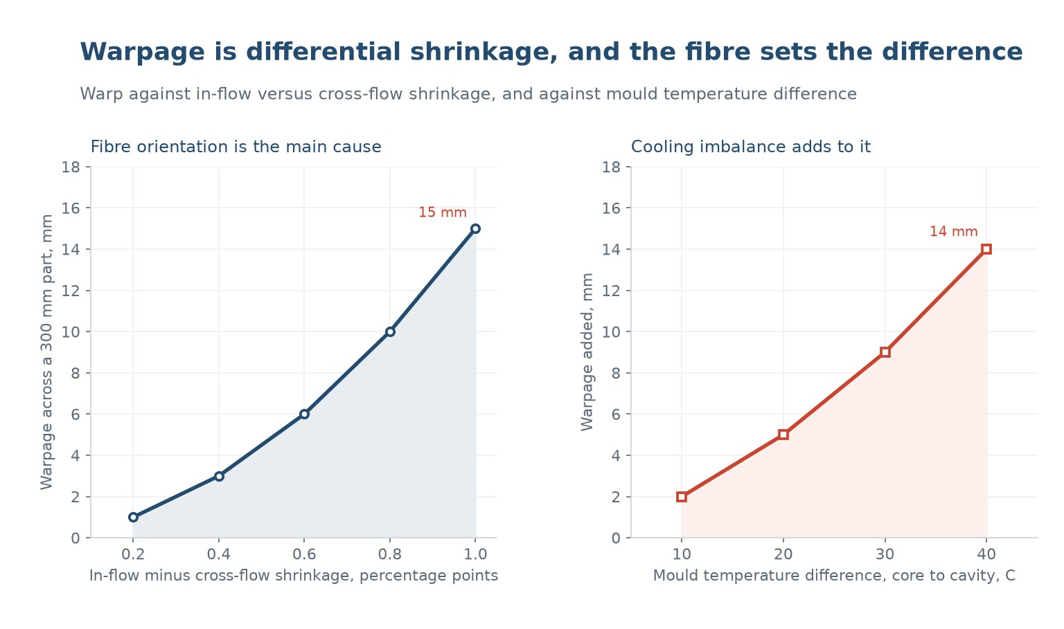
The difference can be large. A 30 percent glass polyamide might shrink 0.3 percent along the flow and 1.3 percent across it, which is a full percentage point of difference. On a 300 mm part that difference warps the part by about 15 mm if the geometry allows it to move, which it usually does.
| Shrinkage difference, points | Warpage on a 300 mm part, mm | Typical material |
|---|---|---|
| 0.2 | 1 | Unfilled amorphous resin |
| 0.4 | 3 | Unfilled semi-crystalline, or low glass content |
| 0.6 | 6 | 20 percent glass |
| 0.8 | 10 | 30 percent glass |
| 1.0 | 15 | 40 percent glass, or a strongly oriented part |
Table 1 — Shrinkage anisotropy against warpage, for a part free to move.
The way to reduce it is to reduce the orientation, not to reduce the shrinkage. A higher melt temperature, a slower fill and a hotter mould all give the fibres more time to relax, and a gate position that produces a more radial flow pattern gives a more balanced orientation. None of them removes the effect entirely, which is why glass-filled parts are designed with warp in mind rather than hoping to process it out.
Cooling imbalance
If the cavity side of the mould is 20 °C hotter than the core side, the part cools unevenly through its thickness. The face against the hot side stays soft longer, so it shrinks more after ejection, and the part curls towards the hot side. That is the mechanism behind the classic warped tray: hot on one face, cold on the other, and the part looks like a shallow dish.
The magnitude is significant. A 10 °C difference between the two faces adds about 2 mm of warp to a 300 mm part, 20 °C adds 5, 30 adds 9 and 40 adds 14. Those are not unusual differences: a mould with cooling channels only on one side, or with a blocked channel, will easily reach 20 °C.
The fix is to balance the cooling, which means measuring the two faces rather than the water. A contact thermometer on the cavity and core surfaces after a run will show the difference, and a mould with independent circuits on each half can then be trimmed. It is one of the cheapest fixes in the whole subject and one of the least often done.
The packing gradient
The third source is pressure. Material near the gate is packed at the full packing pressure; material at the last point to fill is packed at whatever pressure survives the pressure drop along the flow path. That difference in density becomes a difference in shrinkage, and a part with a strong gradient shrinks more at the far end than at the near end.
The symptom is a part that is tapered rather than bowed: one end is wider or thicker than the other. It is common in long, thin parts with a single gate at one end, and it is the reason a long part often wants a gate in the middle rather than at the edge.
The fixes are gate position, gate size and packing profile. A larger gate stays open longer and transmits pressure further; a gate in the middle halves the flow length; and a packing profile that holds pressure while the gate is open and then decays gently avoids over-packing the near end while the far end is still filling.
Design rules that reduce it
Warpage is much easier to design out than to process out, and the rules are mostly about symmetry.
- Keep the wall uniform. A part with a thick rib on one side and a thin wall on the other will warp towards the thick side.
- Use a symmetric rib pattern, or ribs on both faces, so the shrinkage is balanced about the neutral axis.
- Avoid large flat areas in glass-filled materials; a shallow crown or a rib grid breaks up the free length that can bow.
- Put the gate where the flow is balanced, ideally in the centre of a symmetric part, so the orientation pattern is symmetric.
- Design cooling into both halves of the tool from the start, with independent circuits, rather than adding it later.
- If the part must be flat, design a fixture or a post-cooling jig into the process, and accept that the mould alone will not hold it.
The last point is the honest one. Some parts cannot be moulded flat, and the industry answer is a cooling fixture that holds the part while it reaches room temperature. That is a legitimate production solution, not a failure of the mould, and it is much cheaper than a tool redesign if the warp is modest.
Measuring it
Warpage is measured against a datum, and the choice of datum is where arguments start. The useful measurement is the maximum deviation from a plane fitted to the part as it sits in its assembly, because that is what affects whether it fits. A flatness measurement on a free-standing part overstates the problem, because a part that is bolted down flat may be perfectly acceptable.
| Metodo | What it measures | When to use it |
|---|---|---|
| Feeler gauge on a surface plate | Gap under the part at its own weight | Quick check on a flat part |
| CMM or a scanning arm | Deviation from a fitted plane, and the shape | When the warp mode matters, not just the magnitude |
| Height gauge at defined points | A simple before-and-after comparison | Process trials and DOE work |
| Assembly trial | Whether it actually fits | The only test that matters for a bolted part |
Table 2 — Warpage measurement methods and what each one is good for.
The shape of the warp is more informative than the magnitude. A saddle (high at two opposite corners) points at orientation. A bowl (high in the middle) points at cooling or packing. A twist points at asymmetric cooling. Reading the shape tells you which of the three causes to attack, and it takes a straight edge and two minutes.
What causes warpage in injection molding?
Differential shrinkage. The material shrinks differently along and across the flow, the two faces cool at different rates, and the packing pressure varies from the gate to the last point to fill.
Why do glass-filled parts warp more?
Because the fibres orient with the flow and resist shrinkage along their length. A 30 percent glass polyamide can shrink 0.3 percent in flow and 1.3 across it, which warps a 300 mm part by about 15 mm.
Does mould temperature cause warpage?
Yes. A 20 °C difference between the cavity and core faces adds about 5 mm of warp to a 300 mm part, and a 40 °C difference adds 14.
How do I tell which cause is dominant?
Look at the shape. A saddle points at fibre orientation, a bowl at cooling imbalance, and a taper at a packing gradient.
Can warpage be processed out?
Partly. Hotter melt and mould, slower fill and better packing all help, but a strongly anisotropic part will still warp. Design and a cooling fixture are usually needed as well.
Should I measure warp on a free part or bolted down?
Both, but the bolted measurement is the one that decides whether it fits. A part that is flat when clamped may be perfectly acceptable even if it bows when free.
A part that will not stay flat?
Send the drawing, the material and a photo of the warp. We will tell you whether it is orientation, cooling or packing, and which of the three fixes is cheapest.
Continue reading
- Injection Molding Tolerances: What Is Actually Achievable
- Glass-Filled Nylon Injection Molding: Fibre Breakage, Warp and Tool Wear
- Cooling Time in Injection Molding: The Calculation That Sets Cycle Time
- Injection Molding Defects: 12 Problems, Their Causes and Fixes
- PBT and PET Injection Molding: Glass Fibre, Drying and Warpage




 IT
 EN
 ES
 FR
 DE
 PT
 AR
 RU
 JA
 KO
 NL
 TR
 PL
 ID
