
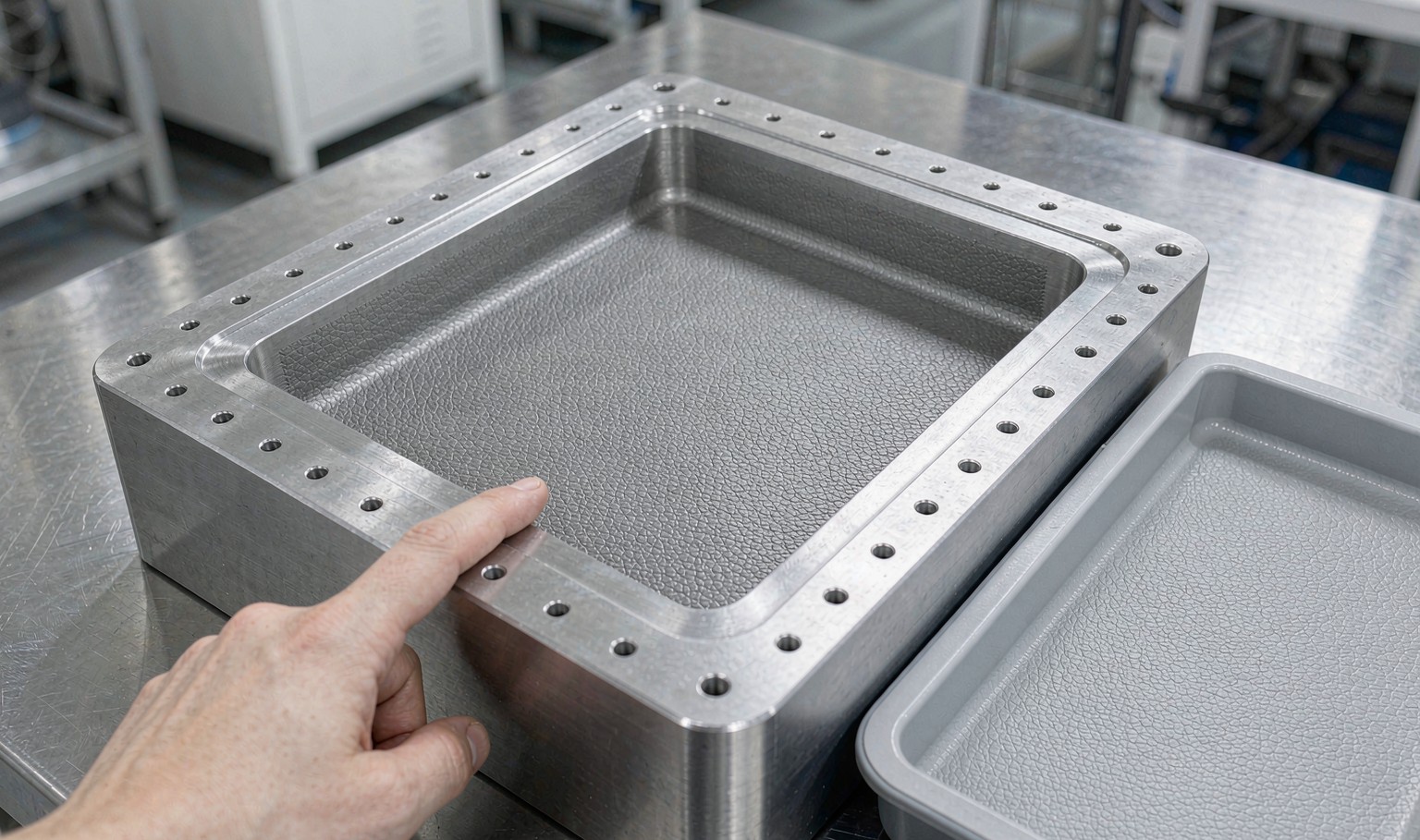
Texture is a depth, not a look
A texture sample is judged by eye, and the eye is a poor judge of depth. Two grains that look identical on a colour chip can differ by a factor of three in peak-to-valley depth, and depth is what decides whether the texture survives forming, whether it releases from the tool and whether it hides a flow mark.
The industry convention is to describe grain by a depth range in micrometres, or by a named standard such as a VDI or MT scale, and both are attempts to put a number on the same thing. What matters for a vacuum forming tool is the peak-to-valley depth and the draft angle of the grain walls, because those two decide how much of the texture reaches the part and how easily it comes off the tool.
A grain that is deep but has vertical walls will hold the part. A grain of the same depth with walls at 10 to 15 degrees will release cleanly. That is why two tools cut to the same depth can have completely different release behaviour, and why depth alone is not a specification.
How grain is put into a tool
There are three routes, and they cost very differently. The cheapest is to use a grained aluminium plate and machine the pocket into it, which gives a uniform grain on the pocket floor but a cut edge where the machining crosses it. The most flexible is to etch the tool after machining, which puts grain anywhere the resist can be applied. The most expensive is to hand-texture, which is used for leather reproductions and grain that has to match a physical sample.
Etching is a chemical process and it is not perfectly uniform. Grain depth varies with local bath agitation and with the alloy, and on a large tool the variation across the face can be 15 to 20 percent. That variation shows up in the part as a texture that is deeper in one corner, and it is worth measuring on the tool before blaming the forming.
Machining a grain into a tool directly is possible with a small ball-nose cutter and a long program, and it gives a repeatable, defined pattern. It is used for geometric textures such as a diamond or a line pattern, where the geometry can be described exactly. For a leather grain, hand texturing or etching remains the practical route.
| Méthode | Depth consistency | Meilleur pour |
|---|---|---|
| Grained plate, machined | Uniform on the floor, cut at edges | Flat panels, simple pockets |
| Chemical etch | Plus or minus 15-20% across a large face | Most production tools |
| Hand texturing | Depends entirely on the toolmaker | Leather reproduction, sample matching |
| Machined pattern | Exact and repeatable | Geometric and line textures |
Table 1 — How the grain gets into the tool, and what it costs in consistency
What the sheet does with it
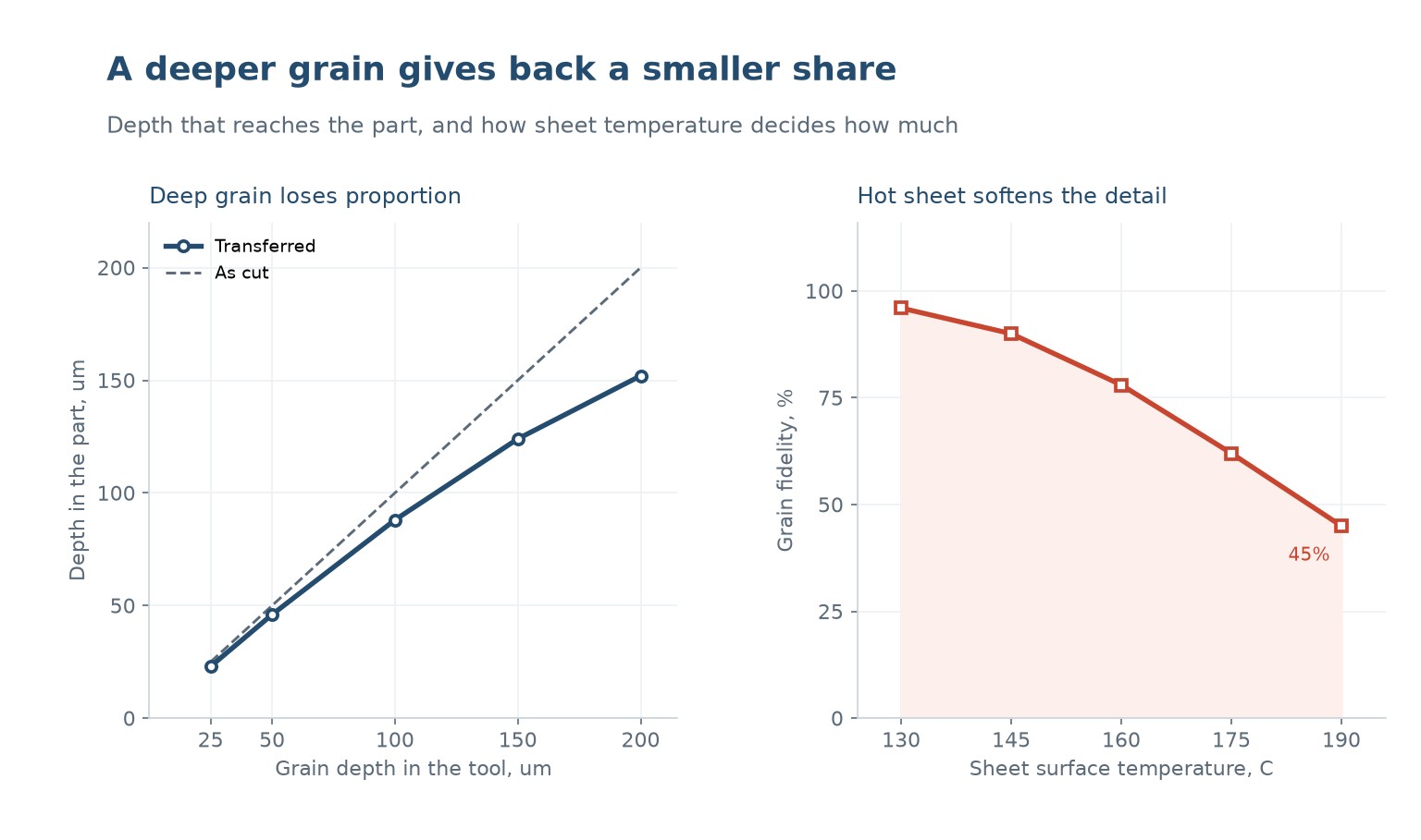
The sheet does not copy the tool. It stretches over it, and stretching thins the wall and flattens the detail. A 50 micrometre grain in the tool comes back at about 46 micrometres in the part, because the local stretch over such a shallow feature is small. A 200 micrometre grain comes back at about 152, because the sheet has to bridge a deeper valley and the walls of that valley are where the thinning happens.
The transfer ratio therefore falls as the grain gets deeper, from about 92 percent at 50 micrometres to about 76 percent at 200. This is the opposite of the intuition that a deeper grain gives a more pronounced texture in absolute terms, and it is why a customer who asks for a deeper grain to get a stronger effect often gets a slightly stronger effect and a much thinner wall in the grain valleys.
The second factor is sheet temperature. A hot sheet is soft and copies detail well; a cool sheet is stiff and bridges over it. At 130 C the fidelity is close to 96 percent of what the tool can give; at 190 C it is down to 45, because the sheet is soft enough to sag into the vacuum holes and stretch away from the grain.
Draw ratio and the grain that disappears
Grain survives where the sheet does not stretch, and disappears where it does. On a shallow tray, the base stretches very little and keeps its grain; the corners stretch most and lose it. The result is a part with a textured base and polished corners, which is a common and unwelcome surprise on a first-off sample.
The fix is usually to accept the variation and design around it, or to reduce the draw. Increasing the grain depth to compensate does not work well, because the corners are stretching more than the base by a factor that no depth can match, and the deeper grain costs wall thickness everywhere.
Where a uniform texture matters, the tool is often textured only where the draw is low, and the high-draw regions are left smooth or given a shallower grain. That is a deliberate design decision made on the tool, and it is much cheaper than trying to fix it with process settings.
Textured tools need different venting
A textured surface is a surface with thousands of small closed volumes in it. Air trapped between the sheet and the grain has nowhere to go except along the grain channels to a vent, and if the grain is fine and the vents are far apart, the air does not get out before the sheet sets.
The symptom is a texture that looks right but has a sheen in patches, or a part with visible air entrapment in the deepest grain areas. The cause is not the vacuum pump; it is the path length from the middle of a grain field to the nearest vent.
The remedy is more vents, smaller and more evenly distributed, and a slower evacuation so the air has time to travel. On a heavily textured tool the vent spacing is often halved compared with a smooth tool of the same size, which is a tool cost that is easy to forget when the texture is added late in the project.
| Tool surface | Vent spacing | Evacuation time |
|---|---|---|
| Smooth | 50-75 mm | Fast, under 1 s |
| Fine grain, under 50 um | 30-40 mm | Modéré |
| Deep grain, over 150 um | 20-25 mm | Slow, 2-3 s |
| Heavy leather reproduction | 15-20 mm | Slowest, and often staged |
Table 2 — Vent spacing has to follow the grain
Specifying texture so it survives
Specify the depth in micrometres, the draft of the grain walls and the area where the texture is required. A sample chip is not a specification, because a chip is flat and unstretched and the part is neither.
Say which surface is textured and which is not, and expect the transition to be visible. A tool that is textured on one face and polished on the other will show a line at the boundary, and that line moves with the draw.
Finally, agree the acceptance method. Grain is usually judged by comparison with a physical master under a defined light, and that master should be a formed part, not a flat chip. A master made from the actual tool, formed at production conditions, is the only reference that settles the argument.
Can a smooth tool be textured later?
Yes, by etching or by hand texturing, but the tool has to be stripped and the vents may need to be added or moved. Texturing a tool that was designed without grain usually means the vent spacing is wrong for the texture, and the parts show air entrapment until the vents are revised.
Why does the texture look different on the second shot?
Because the tool is hotter or the sheet is cooler, or both. Grain fidelity is sensitive to sheet temperature, and a tool that has just come up to temperature forms differently from a cold one. The first few shots of a run are usually not representative.
Does grain depth affect wall thickness?
Yes, locally. The sheet has to stretch into the grain valleys, so the wall is thinner at the bottom of a deep grain than at the surface. On a 200 micrometre grain this can be 10 to 15 percent of the local wall, which matters on a thin part.
How do you measure grain depth on a part?
With a profilometer or a confocal microscope on a cut section, not with a visual comparator. A comparator tells you whether two textures look alike, not how deep either one is, and depth is what the specification should be written in.
Can texture hide flow marks and sink?
It hides small ones and exaggerates large ones. A fine grain breaks up the specular reflection that makes a flow mark visible, but a deep grain on a surface that is sinking will show the sink as a flattened area where the grain did not fill.
Is a textured part harder to demould?
It is, because the grain adds mechanical keying. That is why textured tools need more draft, typically 1 to 2 degrees extra, and why a texture added to an existing tool can turn a part that released cleanly into one that sticks.
A texture that will not survive the draw?
Send the grain sample, the part drawing and the draw depth. We will tell you what depth will still be visible at the corners, and where the tool should be left smooth.
Continue reading
- Mould Venting Design: Why Vent Area Beats Vacuum Power
- Vacuum Holes in a Forming Tool: Size, Spacing and the Marks They Leave
- Thermoforming Mould Temperature Control: Hot Tools, Sharp Detail
- Thermoforming Demoulding: Draft, Ejection and the Part That Sticks
- Custom Vacuum Forming: Tools, Tolerances and Volumes




 FR
 EN
 ES
 DE
 PT
 AR
 RU
 JA
 KO
 IT
 NL
 TR
 PL
 ID
