
- 1. The band is written in millimetres
- 2. Where the numbers in the standard come from
- 3. Why a percentage band fails at small diameter
- 4. Wall thickness is the measurement that decides the reject
- 5. Ovality is a separate number for a reason
- 6. Measuring it: the check that settles arguments
- 7. What actually moves the wall
The band is written in millimetres
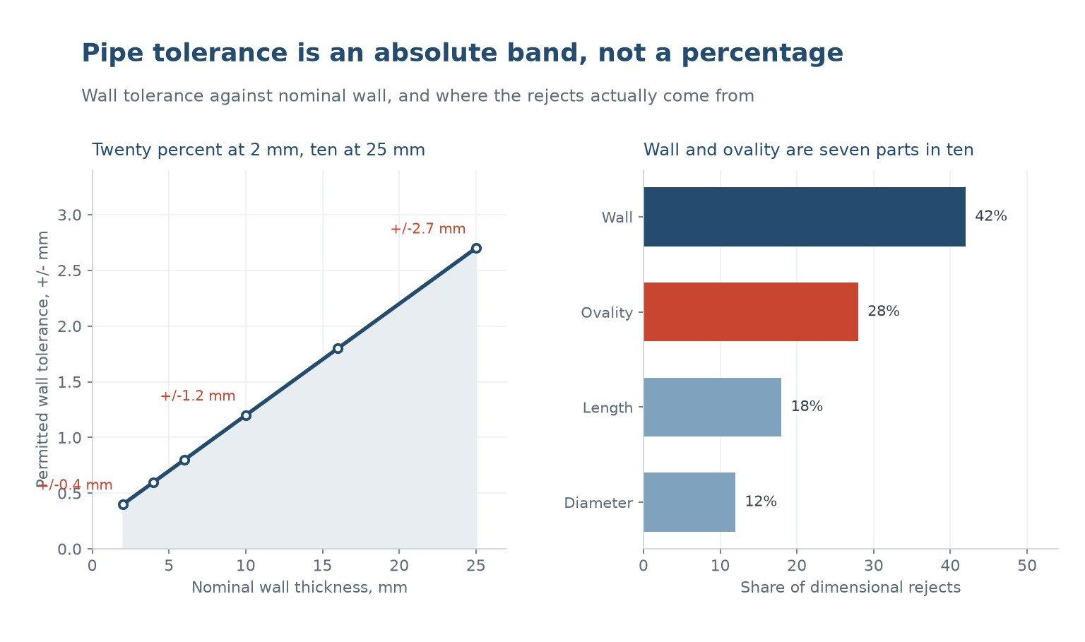
Open a pipe standard and the wall tolerance is not a percentage. It is a pair of numbers in millimetres, or a single number applied to a nominal wall, and it does not scale the way a purchaser expects it to. A 2 mm wall might be permitted plus or minus 0.4 mm. A 10 mm wall gets plus or minus 1.2. A 25 mm wall gets plus or minus 2.7.
Those numbers are not arbitrary. They come from what an extrusion line can hold, and an extrusion line's errors are mostly fixed rather than proportional. Die concentricity is a fixed offset in millimetres. Sizing sleeve wear is a fixed number of microns per thousand metres. Melt temperature variation produces a wall change that depends on the drawdown, not on the wall itself. None of these get bigger because the pipe got bigger.
So the band grows with the wall, but sub-linearly, and the percentage it represents falls. That is the whole story of pipe tolerancing, and almost every argument about a rejected lot comes from one side reading the standard as a percentage and the other side reading it as a band.
Where the numbers in the standard come from
Most pipe standards use one of two shapes. Pressure pipe standards usually give an asymmetric band that never allows the wall to go thin, because thin wall is what fails the hydrostatic test: something like nominal to nominal plus a fixed allowance. Non-pressure and conduit standards usually give a symmetric band, because nothing is being pressurised and the wall only has to be stiff enough.
The fixed allowance in the pressure case is there to absorb the fact that a pipe that measures thin at one point around the circumference will fail there, and the failure is not gradual. A pipe rated at 16 bar with a 10 percent thin patch is not a 14.4 bar pipe; it is a pipe that will burst at the thin patch at some temperature and some time that you cannot predict from the outside.
| Nominal wall, mm | Typical permitted band, mm | Expressed as a percentage | What it means on the line |
|---|---|---|---|
| 2.0 | +/- 0.4 | 20 percent | The band is wider than the process noise, and the gauge resolution is the limit |
| 4.0 | +/- 0.6 | 15 percent | Comfortable; most lines hold this without adjustment |
| 6.0 | +/- 0.8 | 13 percent | Die concentricity starts to matter more than screw speed |
| 10.0 | +/- 1.2 | 12 percent | Cooling asymmetry starts to show as ovality before it shows as wall |
| 16.0 | +/- 1.8 | 11 percent | Sag in the calibrator becomes the dominant error |
| 25.0 | +/- 2.7 | 11 percent | The band is generous, and the rejects move to ovality instead |
Table 1 — The band widens with the wall but the percentage narrows, which is why the two readings of the same standard disagree.
Note what happens at the bottom of that table. At 2 mm the band is 0.8 mm wide in total. If the target is 2.0 and the band is plus or minus 0.4, the process has to sit inside a 0.8 mm window all shift, on a product running at thirty metres a minute. That is not generous, it is tight, and it is tight in a way that a percentage reading would hide.
Why a percentage band fails at small diameter
Suppose a buyer writes the specification as plus or minus 10 percent because that is what they remember from a large-diameter job. On a 25 mm wall that is 2.5 mm, which is close to the standard and easy to hold. On a 2 mm wall it is 0.2 mm, which is not.
A 0.2 mm total band on a 2 mm wall means plus or minus 0.1 mm. The ultrasonic gauge used to check it typically has a resolution of 0.01 mm and an accuracy of plus or minus 0.05 mm on a good day, with a couplant and a clean surface. So a third of the permitted band is inside the measurement uncertainty. Two labs will disagree about the same pipe, and both will be right.
The mechanical side is worse. To hold plus or minus 0.1 mm on a 2 mm wall you need the die concentric to better than 5 percent, the vacuum in the calibrator stable to a few millibar, the haul-off to within a fraction of a percent, and the melt temperature to within a degree. A line that does all of that is a line that is being run carefully for a reason, not a line that is running a commodity pipe.
This is why the standards use a band with a floor rather than a percentage. The floor acknowledges that there is a minimum error budget which no amount of care removes, and that below a certain wall the band has to stop narrowing.
Wall thickness is the measurement that decides the reject
In a typical pipe plant, wall is not the only dimensional check but it is the one that generates most of the rejections. Wall and ovality together account for roughly seven of every ten dimensional rejects; length and diameter make up most of the rest.
The reason is that wall is the variable with the most consequences. It sets the pressure rating through the hoop stress equation, it sets the ring stiffness through the second moment of area, it sets the socket fit, and it sets the weight, which is what the customer is actually paying for. A pipe that is 8 percent heavy is a pipe that costs 8 percent more resin and delivers nothing extra, and a pipe that is 8 percent light is a pipe with a claim attached.
| Reject type | Share of dimensional rejects | Usually caused by | First thing to check |
|---|---|---|---|
| Wall thickness | 42 percent | Drawdown, die concentricity, haul-off drift | Line speed against the last recorded set point |
| Ovality | 28 percent | Cooling asymmetry, sag, stacking | Calibrator vacuum and the spray pattern |
| Length | 18 percent | Cutter encoder, thermal contraction after cutting | Cut length at the measured temperature, not at 20 °C |
| Diameter | 12 percent | Sizing sleeve wear, vacuum level | Sleeve bore against the last measurement |
Table 2 — Where dimensional rejects actually come from, in the order they should be investigated.
There is a useful discipline in that table. Wall and ovality are process variables; length and diameter are mostly equipment variables. If a lot is failing on wall, the answer is in the line settings. If it is failing on diameter, the answer is usually a worn sleeve, and no amount of process adjustment will fix it.
Ovality is a separate number for a reason
Ovality is the difference between the largest and smallest diameter at a section, usually expressed as a percentage of the nominal diameter. It is specified separately from wall because the two fail independently. A pipe can be perfectly on-wall around its whole circumference and still be visibly out of round, and a pipe can be round and have a wall that varies by 15 percent around the circumference.
The causes are different too. Ovality comes from the pipe being cooled unevenly, from sagging under its own weight while still soft, from being pulled through the haul-off before it is stiff, and from being stacked or coiled while it is still relaxing. Wall variation comes from the die, the drawdown and the melt.
The two interact in one specific way that catches people out. A two-point micrometer measures wall at two opposite points. On an oval pipe, those two points are not representative, and the reading can be comfortably inside tolerance while the thin points, ninety degrees away, are outside it. This is the single most common reason a pipe passes at the plant and fails at the customer's incoming inspection.
Measuring it: the check that settles arguments
The method that ends disputes is a full-circumference ultrasonic scan at three stations along the length, eight points per station, on a pipe that has been conditioned at 23 °C for at least an hour. That gives twenty-four wall readings, a maximum, a minimum, a mean and a spread, and from those you can compute both the wall tolerance and the eccentricity.
| Méthode | Typical accuracy | What it catches | What it misses |
|---|---|---|---|
| Two-point micrometer | +/- 0.01 mm on the reading | Wall at two points, ovality if you rotate | Thin patches at ninety degrees to the measurement plane |
| Ultrasonic thickness gauge | +/- 0.05 mm with couplant | Wall at any point, on a finished pipe | Delamination and voids, which read as thin wall |
| Full-circumference scan | +/- 0.02 mm, 8 to 64 points | Eccentricity, the true maximum and minimum | Nothing important, but it takes minutes per pipe |
| Laser diameter gauge | +/- 0.005 mm | Diameter and ovality continuously, in line | Wall, unless paired with a second gauge |
| Weight per metre | +/- 0.5 percent | Average wall over a length, cheaply | Any local variation at all |
Table 3 — Measurement methods, and the specific defect each one is blind to.
Weight per metre deserves a mention because it is the check that most plants actually run, and it is the one that hides the most. It gives you the average wall over the cut length with great precision, and it tells you nothing about whether that average is made of a uniform wall or a wall that is 20 percent thick on one side and 20 percent thin on the other. Both pipes weigh the same. Only one of them passes the hydrostatic test.
What actually moves the wall
If a line is drifting out of wall tolerance, there are five levers and they are worth checking in this order, because the first one accounts for more drift than the other four combined.
- Drawdown. Wall moves inversely with line speed for a fixed extruder output. A 1 percent error in line speed is a 1 percent error in wall, and line speed is the setting most often changed by hand and least often recorded.
- Extruder output drift. Screw wear, a partially blocked screen pack or a barrel heater going soft will move output by a few percent over a shift without any alarm.
- Die concentricity. This shows as a once-per-revolution pattern in the wall, and it is corrected with the die adjustment screws, not with the process.
- Calibrator vacuum. Too little vacuum and the pipe does not seat against the sleeve, so the wall floats. Too much and the pipe is dragged, which thins it.
- Melt temperature. A 10 °C rise lowers the melt viscosity, raises output at fixed screw speed and increases drawdown, so the wall falls twice for the same change.
The practical rule is to log line speed and extruder output every hour, not just at start-up, and to plot the wall against the ratio of the two. When the ratio is stable and the wall is not, the problem is downstream in the calibrator or the die. When the ratio itself drifts, the problem is upstream and no die adjustment will help.
Is a wall tolerance a percentage or a fixed number?
In almost every pipe standard it is a fixed band in millimetres, sometimes with a percentage cap at large walls. Reading it as a flat percentage gives a band that is far too tight on thin walls and far too loose on thick ones.
Why does my pipe pass at the plant and fail at the customer?
Usually ovality. A two-point measurement on an oval pipe can read inside tolerance while the thin points, ninety degrees away, are outside it. Full-circumference ultrasonic scanning is the only way to catch it.
What causes wall to vary around the circumference?
Die concentricity first, then uneven cooling. A once-per-revolution pattern points at the die; a pattern that follows the spray nozzles points at the calibrator.
How often should wall be measured?
At start-up, after any setting change, and then at a frequency set by the capability of the line. A line running at a Cpk above 1.33 on wall can go hours; a line at 1.0 needs checking every drum.
Does a heavier pipe mean a better pipe?
No. Extra wall beyond the specification is extra resin, extra weight and extra cost, and it does not improve the pressure rating because the rating is set by the minimum wall, not the average.
Can wall tolerance be tightened by running slower?
Slower running reduces drawdown and gives the calibrator more time, so the spread narrows. It also raises cost per metre. The right question is whether the standard's band is being read correctly before spending money on line speed.
Fighting a wall tolerance that the line will not hold?
Send the nominal wall, the diameter and the standard you are working to. We will tell you whether the band is achievable on that geometry, and where the drift is most likely coming from.




 FR
 EN
 ES
 DE
 PT
 AR
 RU
 JA
 KO
 IT
 NL
 TR
 PL
 ID
