The problem
Symptom. A brass terminal moulded into a connector reads 0.28 mm off true position on the buyer's CMM, while the moulder reports it in tolerance because the drawing defines no measurement datum.
What it costs. Connector pins then miss their mating header at assembly, so a batch is rejected and the dispute stalls on whose datum is correct rather than on the core shift that moved the insert.
This guide links core shift to terminal drift, gives the support-pin and datum details for the drawing, and sets a +/- 0.10 mm position acceptance test on the CMM.
What a terminal position dispute looks like
A brass terminal held by a single core pin bends under 90 MPa cavity pressure at 80 mm/s fill. True position drifts 0.28 mm from nominal, while a +/- 0.10 mm drawing limit is measured from datums nobody agreed.
| Observed result | Most likely cause | First check on the order |
|---|---|---|
| CMM reads 0.28 mm off position | Core shift under high cavity pressure | Check support pins and fill speed |
| Moulder passes, buyer rejects | No A/B/C datum on the drawing | Re-measure both from one datum scheme |
| Drift worse on one cavity | A worn or missing support pin | Log position by cavity number |
| Position moves after 48 h | Conditioning not defined | Re-measure at 23 C / 50 % RH |
Table 1 - Reading a terminal-position dispute before re-cutting
Need a fixed price for this moulded part?
Send the 2D drawing, resin grade and annual volume. Our engineers return a DFM review, a material recommendation and a written quotation you can compare line by line.
Separate core shift from a measurement-datum error
Measure the same 10 connectors on a CMM using datums A, B and C, then again from the moulder's edge reference. A constant 0.28 mm offset that changes with the datum is a definition gap, not only a shifted insert.
A five-step diagnostic sequence
- Pull the drawing and both CMM reports.
A 0.28 mm buyer reading against no datum is a definition gap as much as a shifted terminal. - Re-measure 10 connectors from one A/B/C scheme.
Compare the 0.28 mm offset from an agreed seating face, long edge and tooling hole. - Check the insert support in the tool.
Confirm three 2.0 mm pins at 120 degrees; a single core pin lets the 0.8 mm terminal bend. - Lower melt-front load one step at a time.
Drop fill from 80 to 45 mm/s and cavity pressure from 90 to 60 MPa, then re-measure. - Re-qualify against the +/- 0.10 mm limit.
Report 10 parts per cavity on the CMM after 48 h at 23 C / 50 % RH.
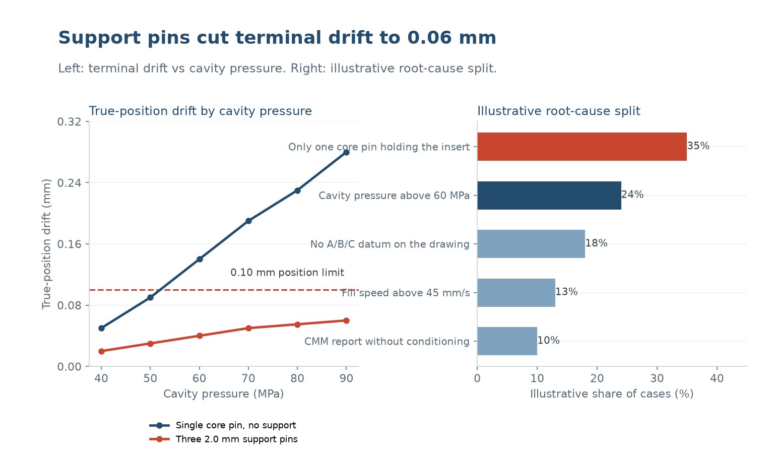
The chart below is a typical result from that measurement step. Use it to separate a design limit from a setting that can still be recovered.
Datum and tolerance details for the drawing
Put a datum scheme on the drawing: A the moulded seating face, B a long edge, C a tooling hole, and a true-position tolerance of +/- 0.10 mm on the 4 mm wide terminal, measured after 48 h at 23 C / 50 % RH.
| Paramètres | Typical target | What goes wrong outside it |
|---|---|---|
| True-position tolerance | +/- 0.10 mm to datums A/B/C | A 0.28 mm drift misses the mating header |
| Terminal support | Three 2.0 mm pins at 120 degrees | A single core pin bends under 90 MPa |
| Cavity pressure and fill speed | 60 MPa, 45 mm/s | 90 MPa and 80 mm/s shift the insert |
| CMM conditioning | 48 h at 23 C / 50 % RH | Unconditioned parts move after moulding |
Table 2 - Position parameters for the part drawing
Support pins and pressure that move the insert
Three 2.0 mm support pins at 120 degrees restrain a 0.8 mm thick terminal against the melt front. Dropping cavity pressure from 90 to 60 MPa and fill speed from 80 to 45 mm/s cuts the residual drift to 0.06 mm.
| Decision | Effect on position | Trade-off |
|---|---|---|
| Add three 2.0 mm support pins | Holds drift near 0.06 mm | Tool change, 3 insert seats |
| Drop fill speed 80 to 45 mm/s | Cuts melt-front load on the pin | Longer fill, possible weld lines |
| Reduce cavity pressure 90 to 60 MPa | Less insert deflection | Risk of sink over the boss |
| Define A/B/C datums on the drawing | Removes the measurement argument | No hardware cost, needs agreement |
Table 3 - Decisions ranked by tool-change cost
Agree a position acceptance test on the CMM
Agree acceptance before first article: the A/B/C datum scheme, a +/- 0.10 mm true position, a CMM programme at 23 C / 50 % RH after 48 h, and 10 parts per cavity reported against the nominal.
Not sure whether the fault is in the tool or the process?
Send us the drawing, the process window and a few sample parts. We will tell you which change fixes the fault before you commit to a tool modification.
What to send us
- Part drawing with the affected dimension
- Current process settings
- Sample parts from a good and a bad batch
- Annual volume
Recovery actions ranked by tool-change cost
For a batch already moulded, re-measure on the agreed datums and quarantine by cavity. Adding three 2.0 mm support pins needs a tool change, so lower fill speed first and re-qualify position against the 0.10 mm limit.
Before you release this injection moulding job
- A datum scheme A/B/C is defined on the part drawing, not left to the inspector
- A true-position tolerance of +/- 0.10 mm is stated for the 4 mm terminal
- Three 2.0 mm support pins at 120 degrees are dimensioned in the tool specification
- A CMM programme with 48 h conditioning at 23 C / 50 % RH is agreed
- First-article position is reported for 10 parts per cavity against the nominal
Attach this list to the RFQ. Most moulding faults are decided at the drawing stage.
Why does the terminal move after overmoulding?
With one core pin, 90 MPa cavity pressure at 80 mm/s bends the 0.8 mm brass insert, giving 0.28 mm of true-position drift.
Is the dispute really about the datum?
Often both. If the drawing names no A/B/C scheme, the buyer and moulder measure from different references, so add the datum before re-cutting steel.
How much do support pins help?
Three 2.0 mm pins at 120 degrees, plus a drop to 60 MPa and 45 mm/s, hold residual drift near 0.06 mm, inside the +/- 0.10 mm limit.
What conditioning should the CMM report use?
Measure after 48 h at 23 C / 50 % RH, so post-mould shrinkage has settled and both parties read the same number.
Can we fix it by lowering pressure alone?
It buys margin but may add sink over the boss. Support pins restrain the insert mechanically; use settings for the last 0.04 mm.
Who owns a rejected connector batch?
Put it in the order. Name the datum scheme, the +/- 0.10 mm position and the CMM method so a drift is settled by one report.
Get a mouldable part and a fixed quotation
Send us the part file and the failure history. Our engineers will return a DFM review, a material recommendation and a fixed quotation with a defined first-article acceptance test.
To get an accurate quote, send:
- 3D file or 2D part drawing
- Resin grade and any regrind limit
- Annual volume and target unit price
- The failed sample or defect photos
Request a DFM review and quote
Why buyers work with Uplastech
ISO 9001, ISO 14001 and ISO 45001 certified. Founded in 2016, with injection moulding lines in Shanghai and an extrusion plant in Jiangsu. Moulding machines from 90T to 1100T and a maximum shot weight of 5100 g. Samples and a written quotation are available on request.

 FR
 EN
 ES
 DE
 PT
 AR
 RU
 JA
 KO
 IT
 NL
 TR
 PL
 ID