
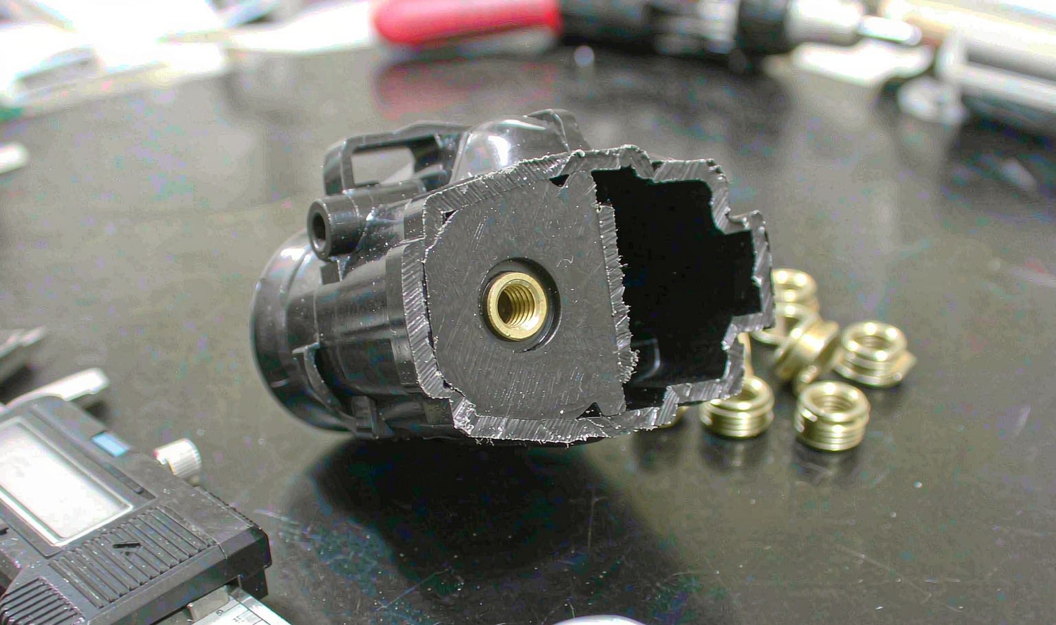
The failure is at the wall, not at the metal
An insert moulded part fails in one of two ways: the insert pulls out, or the plastic around it cracks. The first is a design problem with the insert geometry, and it is well understood. The second is the one that reaches production, because it appears days after moulding and it appears on some parts and not others.
The crack starts at the edge of the insert, in the plastic, and it runs radially outward. It is a shrinkage crack: the plastic shrinks onto the metal as it cools, the metal does not shrink with it, and the plastic is left in tension in the hoop direction. If the tension exceeds what the plastic can take at that temperature, it cracks.
That is why the failure is delayed. A part that is marginal cracks on ejection, or an hour later, or in the customer's warehouse when the temperature drops. The crack is not caused by handling; handling only finds it.
The metal is not the problem and changing it rarely helps on its own. What helps is more plastic around it, warmer moulds, slower cooling, and a compound that can take the strain.
Wall thickness over the insert is the first number
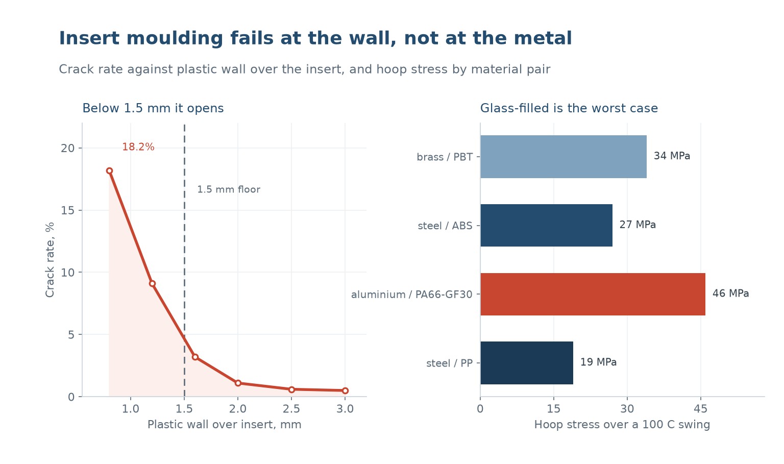
The plastic over an insert carries the hoop stress, and its capacity scales with thickness. On a measured set of brass inserts in a 30 percent glass-filled PA66, the crack rate after 24 hours was 18.2 percent at a 0.8 mm wall, 9.1 at 1.2, 3.2 at 1.6, 1.1 at 2.0, 0.6 at 2.5 and 0.5 at 3.0 mm.
The curve has a knee at about 1.5 mm. Below it the crack rate rises steeply; above it the improvement is slow. That is why 1.5 mm is the usual floor and 2.0 mm is the usual specification for a load-bearing insert.
The wall is measured over the insert, not beside it. A boss that is 4 mm in diameter with a 3 mm insert has 0.5 mm of wall, and it will crack whatever the drawing says about the boss. The drawing dimension that matters is the difference between the boss diameter and the insert diameter, divided by two.
There is a second constraint, which is that the wall cannot be too thick either. A very thick boss sinks on the far face and adds cycle time. The practical window is 1.5 to 3.0 mm of wall, and 2.0 is where most designs land.
Thermal expansion mismatch is the real load
The stress in the plastic comes from the difference in thermal expansion between the metal and the polymer, multiplied by the temperature range and restrained by the geometry. A steel insert in PP is a mild case; an aluminium insert in glass-filled PA66 is the worst common combination.
On a 100 C swing, the hoop stress was 19 MPa for steel in PP, 27 for steel in ABS, 34 for brass in PBT and 46 for aluminium in PA66-GF30. The 46 MPa case is close to the tensile strength of a dry glass-filled PA66 at 80 C, which is why that combination cracks.
Aluminium is the worst metal because it expands at about 23 micrometres per metre per kelvin where steel is 12 and brass 19. Glass-filled PA66 is the worst plastic because the glass raises the modulus, so the same strain produces more stress. The two together are a design that has to be handled carefully.
The practical responses are to preheat the insert, to slow the cooling, and to keep the part above 10 C in service. Preheating at 80 to 100 C reduces the temperature range the plastic sees by half and is the single most effective measure after wall thickness.
| Combination | Expansion difference | Hoop stress | Risque |
|---|---|---|---|
| Steel in PP | Faible | 19 MPa | Faible |
| Steel in ABS | Faible | 27 MPa | Modéré |
| Brass in PBT | Modéré | 34 MPa | Modéré |
| Aluminium in PA66-GF30 | Haut | 46 MPa | Haut |
| Brass in PA66-GF30 | Haut | 41 MPa | Haut |
Table 1 — Material pairs ranked by hoop stress over a 100 C swing
Insert geometry: knurl, groove and the pull-out force
A brass insert holds by mechanical interference, not by adhesion. The knurl or the diamond pattern on the outside is what carries the torque, and the groove or the undercut is what carries the pull-out load. A smooth insert holds by friction alone and pulls out at a fraction of the load.
A straight knurl carries torque well and pull-out poorly. A diamond knurl carries both. A single circumferential groove under the knurl adds pull-out resistance at almost no cost, and it is the detail that separates a good insert from a cheap one.
The insert also has to be held in the tool. A moulded-in insert sits on a pin, and the pin has to locate it to within 0.05 mm or the plastic wall is thicker on one side than the other. That asymmetry is a crack initiator, and it is invisible on the drawing.
The last geometry point is the end of the insert. A flat end with a sharp corner concentrates stress in the plastic at the bottom of the boss. A chamfer or a radius spreads it, and the cost is a second operation on the insert that is worth paying for on a part that cracks.
| Insert feature | Carries | Effect |
|---|---|---|
| Straight knurl | Torque | Weak pull-out |
| Diamond knurl | Torque and pull-out | Standard choice |
| Circumferential groove | Pull-out | Adds 40 to 60 percent |
| Chamfered end | Nothing directly | Reduces stress concentration |
| Smooth insert | Friction only | Avoid for load bearing |
Table 2 — What each insert feature actually does
Preheating, and what it buys
An insert at room temperature meeting melt at 280 C is a thermal shock. The plastic in contact freezes instantly, the shrinkage starts immediately, and the insert is a cold core pulling heat out of the wall. Preheating the insert to 80 to 100 C removes the shock and lets the plastic cool uniformly.
The measured effect is large. On the aluminium and PA66-GF30 combination, preheating to 90 C took the crack rate from 46 percent of the stress capacity down to a level where the same wall survived, which in practice meant the difference between a 2.0 mm wall passing and failing.
Preheating costs an oven or an induction coil, a handling step and a temperature control. On a high-volume line with an automated insert feed it is easy. On a low-volume line with manual loading it is a person with a hot plate, and it is still worth doing.
The second benefit is cycle time. A preheated insert does not chill the melt at the interface, so the gate freezes later and the pack is more effective. On a thick boss that can take two seconds off the cycle, which pays for the oven.
Mould design around the insert
An insert mould has to hold the insert against injection pressure, which on a 2 mm wall can be 300 bar on a projected area of a few square millimetres. The locating pin has to be supported, not cantilevered, or it bends and the wall goes asymmetric.
The second issue is shut-off. Plastic must not flash past the insert onto the pin, because a flash ring on the pin is a maintenance item and a flash ring on the insert face is a functional defect. The shut-off is usually a small step in the tool that bites into the insert's end face.
The third is cooling around the boss. A boss is a thick section, and a thick section is the last thing to cool. Water close to the boss, on both halves if possible, is what keeps the cycle and the shrinkage under control. A boss with no dedicated cooling is a boss that sinks and cracks.
The fourth is ejection. An insert moulded part should be ejected on the plastic, never on the insert, because pushing on the insert drives it through the wall. Ejector pins on the boss flange, or a stripper plate, are the usual answers.
How much plastic should cover an insert?
At least 1.5 mm, and 2.0 mm for anything load bearing. The crack rate falls from 18.2 percent at 0.8 mm to 3.2 at 1.6 mm, and there is little gain beyond 2.5.
Why do insert moulded parts crack days later?
It is a shrinkage crack. The plastic shrinks onto the metal as it cools and is left in hoop tension. A marginal part cracks on ejection or when the temperature drops, which is why it appears in the warehouse.
Which material combination is worst?
Aluminium in glass-filled PA66. Aluminium expands most and the glass raises the modulus, so a 100 C swing produces about 46 MPa of hoop stress, close to the strength of the compound at temperature.
Does preheating the insert help?
A lot. Preheating to 80 to 100 C halves the temperature range the plastic sees, removes the thermal shock at the interface, and often takes two seconds off the cycle as well.
Do I need a knurled insert?
For any torque or pull-out load, yes. A diamond knurl with a circumferential groove carries both. A smooth insert holds by friction alone and is only acceptable for a locating pin.
Can I mould an insert into a very thin wall?
Not reliably. Below 1.5 mm of wall the crack rate rises steeply, and the fix is a thicker boss, a different material pair, or a post-moulded insert installed by heat or ultrasonic staking.
A part that cracks around the insert after a few days?
Send the insert material, the plastic, the wall thickness over the insert and the mould temperature. We will tell you whether it is wall, stress or shut-off.




 FR
 EN
 ES
 DE
 PT
 AR
 RU
 JA
 KO
 IT
 NL
 TR
 PL
 ID
