
Cooling is most of the cycle
On a typical injection moulding cycle, cooling accounts for 50–70% of the total time. Injection is 2–5%, packing and holding is 15–25%, and mould open, ejection and close is 10–20%. If you want to shorten a cycle, cooling is where the time is — and it is also where most of the quality risk is, because cooling too fast creates warpage, sink and internal stress.
What makes cooling unusual is that it is almost entirely predictable. Unlike packing, which depends on part geometry in ways that are hard to model, cooling follows a clean analytical relationship that you can calculate on paper before the mould is cut.
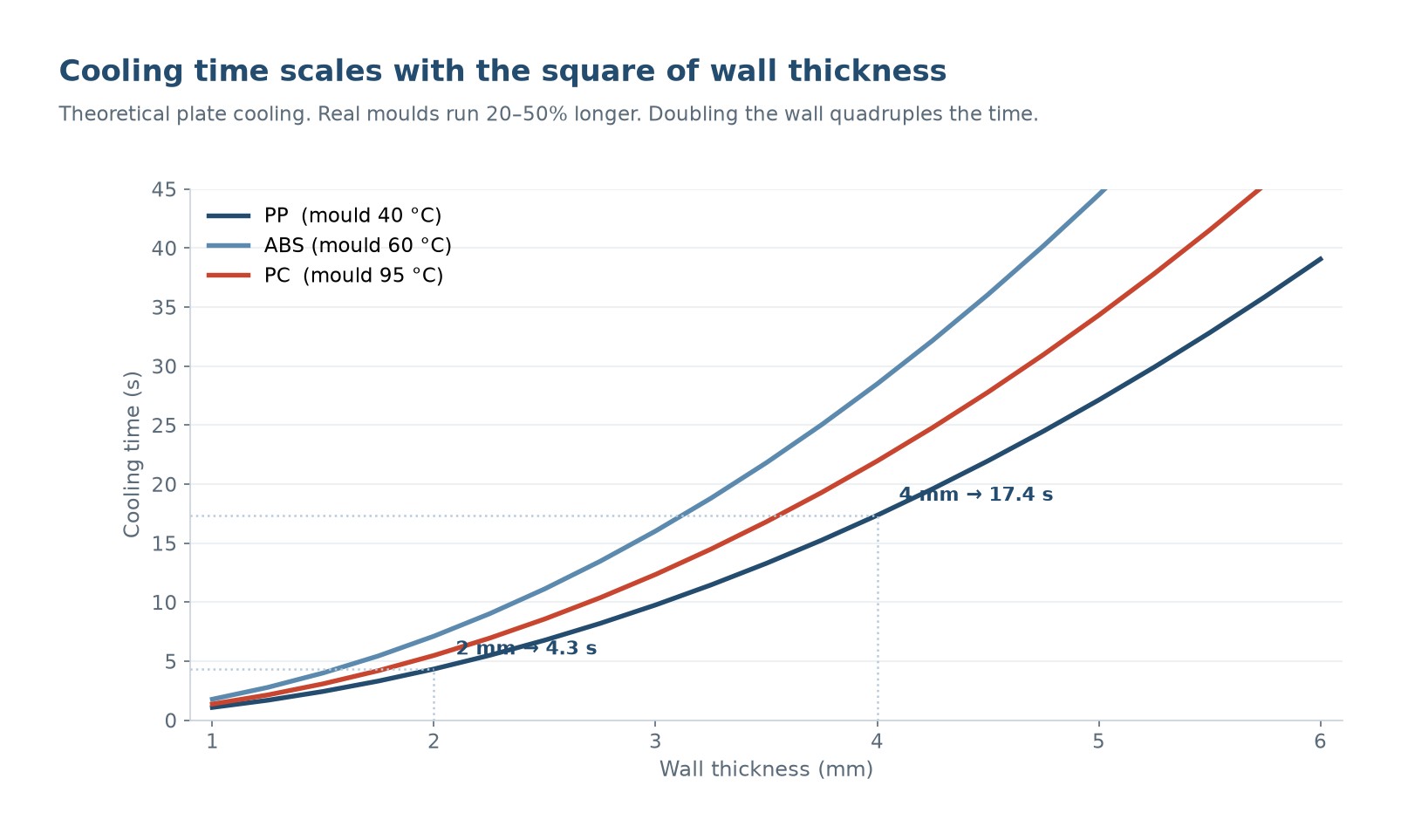
The relationship to remember: cooling time is proportional to the square of wall thickness. Double the wall and you quadruple the cooling time. This is why a 2 mm wall cools in about 5 seconds and a 4 mm wall in about 20 — and why a single thick boss in an otherwise thin part can double the cycle on its own.
The calculation
The standard formula for cooling time of a flat plate is:
t = (h² / (π² · α)) · ln( (4/π) · (Tmelt − Tmould) / (Teject − Tmould) )
Where h is the wall thickness (in metres, but usually half-thickness is used depending on the convention — be consistent), α is the thermal diffusivity of the polymer (m²/s), Tmelt is the melt temperature, Tmould is the mould temperature, and Teject is the temperature at which the part is stiff enough to eject.
The practical version, which is what most moulders actually use, is:
t = (s² / (π² · α)) · ln( (8/π²) · (Tmelt − Tmould) / (Teject − Tmould) )
Where s is the full wall thickness. Both forms appear in the literature; the difference is the geometry assumption (plate cooling from one face vs two). For most parts, the second form with full thickness gives a realistic answer.
| Resin | Thermal diffusivity α (mm²/s) | Melt temp (°C) | Typical mould temp (°C) |
|---|---|---|---|
| PP | 0.09 – 0.12 | 220 | 30 – 50 |
| PE | 0.10 – 0.13 | 210 | 25 – 45 |
| PS | 0.08 – 0.10 | 220 | 30 – 50 |
| ABS | 0.08 – 0.10 | 240 | 50 – 70 |
| PC | 0.10 – 0.13 | 300 | 80 – 110 |
| PA66 | 0.09 – 0.11 | 285 | 80 – 100 |
| POM | 0.10 – 0.12 | 200 | 80 – 100 |
| PBT | 0.08 – 0.10 | 255 | 60 – 90 |
Table 1 — Thermal diffusivity and typical temperatures. The values are close enough across resins that thickness dominates the calculation far more than material choice.
A worked example
Take a PP part with a 2 mm wall, melt at 220 °C, mould at 40 °C, ejected at 90 °C.
Using α = 0.10 mm²/s, s = 2 mm:
t = (4 / (9.87 × 0.10)) × ln( (0.81 × 180) / 50 )
t = 4.05 × ln(2.92) = 4.05 × 1.07 = 4.3 seconds
Now double the wall to 4 mm:
t = (16 / 0.987) × ln( (0.81 × 180) / 50 ) = 16.2 × 1.07 = 17.3 seconds
The wall doubled, the cooling time quadrupled. That is the relationship in action, and it is why a part with a 4 mm section in a 2 mm wall has a cycle time set by the 4 mm section.
| Wall (mm) | PP cooling (s) | ABS cooling (s) | PC cooling (s) |
|---|---|---|---|
| 1.0 | 1.1 | 1.4 | 1.5 |
| 1.5 | 2.4 | 3.1 | 3.4 |
| 2.0 | 4.3 | 5.5 | 6.0 |
| 2.5 | 6.8 | 8.6 | 9.4 |
| 3.0 | 9.7 | 12.4 | 13.5 |
| 4.0 | 17.3 | 22.0 | 24.0 |
| 5.0 | 27.0 | 34.4 | 37.5 |
Table 2 — Calculated cooling times. These are theoretical minimums for a flat plate with ideal cooling; real moulds add 20–50% because of uneven cooling and ejection constraints.
The gap between calculated and actual is where most cycle-time improvement lives. A mould that calculates at 4.3 s and runs at 9 s has a cooling problem — usually unbalanced circuits, poor turbulence, or a hot spot from a thick section.
What actually shortens cooling
There are only four levers, and three of them are about the mould rather than the process.
| Lever | Effect | Practical limit |
|---|---|---|
| Lower mould temperature | Larger temperature difference, faster cooling | Too cold causes short shots, poor surface, high stress |
| Lower ejection temperature | Shorter cooling window | Part distorts or ejects damaged |
| Better cooling circuit design | Higher heat transfer coefficient | Geometry of the part limits where you can put water |
| Turbulent flow | Reynolds number above 10,000 dramatically improves heat transfer | Requires correct flow rate for the circuit diameter |
Table 3 — The four levers. The turbulence one is the most underused: many moulds run water in laminar flow and lose 40% of the achievable heat transfer.
Turbulence deserves the emphasis. Water in a 10 mm channel flowing at 3 l/min is laminar; the same channel needs roughly 12–15 l/min to be turbulent. The heat transfer coefficient in turbulent flow can be three to five times higher, which directly reduces the mould surface temperature recovery time between shots.
The practical check is a flow meter on each circuit and a ΔT measurement across it. A circuit with a ΔT above 3 °C is either flowing too slowly or has a blockage. Both mean the mould is not cooling as designed.
Thick sections, bosses and the parts that set the cycle
A part's cooling time is set by its thickest section, not its average. This is the single most common reason a cycle is longer than expected.
| Fonctionnalité | Effect on cycle | Design response |
|---|---|---|
| Uniform wall | Cycle set by the wall | Best case; design for it |
| Boss at 1.5× wall | Cycle rises ~2× | Core the boss; use a thinner wall with ribs |
| Boss at 2× wall | Cycle rises ~4× | Unacceptable unless the boss is small and isolated |
| Rib at 0.5× wall | Minimal effect | Ribs are the correct way to add stiffness |
| Thick optical section | Cycle dominated by that section | Accept it, or use a different process |
| Metal insert | Extends cooling; the insert holds heat | Pre-heat the insert, or cool it directly |
Table 4 — Features that extend the cycle. The boss rule is the one worth memorising: a boss thicker than 1.2× the nominal wall starts to dominate.
The design response is always the same: replace thickness with geometry. A 4 mm boss that could be a 2 mm wall with four ribs is not just faster to cool — it is lighter, less prone to sink, and uses less material. The cooling time argument is usually the one that convinces a designer, because it translates directly into part cost.
Mould temperature is a quality decision, not a speed decision
Lowering mould temperature shortens the cycle and damages the part. The relationship is not linear and the failure modes are specific.
| Resin | Recommended mould temp (°C) | What goes wrong if too cold |
|---|---|---|
| PP | 30 – 50 | Poor surface, high shrinkage, warpage |
| PE | 25 – 45 | Warpage, poor weld line strength |
| PS | 30 – 50 | Brittleness, flow marks |
| ABS | 50 – 70 | Visible flow lines, low gloss, stress |
| PC | 80 – 110 | Stress cracking, poor surface, short shots |
| PA66 | 80 – 100 | Low crystallinity, dimensional instability |
| POM | 80 – 100 | Post-mould shrinkage, warpage |
| PBT | 60 – 90 | Low crystallinity, poor surface |
Table 5 — Mould temperature ranges. For semi-crystalline resins, a cold mould means incomplete crystallisation, which means the part keeps shrinking after it is measured.
The semi-crystalline resins are the sensitive ones. PA, POM and PBT need a hot mould not for surface quality but for crystallinity. A part moulded in a cold tool has an amorphous skin and a partially crystalline core, and it continues to crystallise and shrink for days. Dimensions measured at the machine will not match dimensions measured a week later, and the customer will find out first.
Verifying the cooling time in the tool
The calculation tells you what is possible. The tool tells you what is happening. Three measurements close the gap.
Cavity surface temperature. An infrared probe or a contact thermocouple on the cavity surface immediately after ejection. If it is above the resin's ejection temperature, the cooling time is too short or the circuit is not working.
Circuit ΔT. Temperature difference between inlet and outlet on each circuit. Above 3 °C means insufficient flow. Above 5 °C means a real problem.
Part temperature at ejection. Measured with a contact probe on the thickest section. If it is above the recommended ejection temperature, the part will warp after ejection and the cycle is being pushed too hard.
How do I calculate cooling time?
Use t = (s² / (π² · α)) × ln( (8/π²) × (Tmelt − Tmould) / (Teject − Tmould) ), where s is wall thickness, α is thermal diffusivity (roughly 0.10 mm²/s for most plastics), and the temperatures are in °C. The result is a theoretical minimum; real moulds run 20–50% longer.
Why does doubling wall thickness quadruple cooling time?
Because heat has to conduct out through the wall, and conduction distance enters the equation squared. Twice the distance means four times the time for the same temperature drop. It is the same reason a thick steak takes disproportionately longer than a thin one.
What is a typical cooling time for a 2 mm PP part?
About 4–5 seconds theoretical, and 6–9 seconds in a real mould with average cooling. If you are running 15 seconds on a 2 mm PP part, the mould cooling is not working and there is money on the table.
Does colder water always cool faster?
No. Flow rate and turbulence matter more than supply temperature in most moulds. Water at 50 °C in turbulent flow removes more heat than water at 20 °C in laminar flow. Check flow rate and circuit ΔT before lowering the chiller set point.
Why does my part still warp after correct cooling time?
Because cooling is uneven, not because it is too short. Different wall sections cooling at different rates create differential shrinkage. The fix is balanced circuits, baffles or bubblers in cores, and a mould temperature that suits the resin — not simply more time.
Can I cool a thick section faster with a bubbler?
A bubbler or baffle in a core improves heat transfer in a deep feature, but it cannot beat the physics of thickness. A 6 mm section will still take about 40 seconds. The real answer is to redesign the section thinner.
How much does cooling time affect part cost?
On a machine running at $40–80 per hour, one second of cycle time on a 30-second cycle is roughly 3% of machine cost per part. On a high-volume part that is significant. Cooling optimisation is usually the highest-return improvement available on an existing mould.
What is the difference between cooling time and hold time?
Hold time is how long packing pressure is applied after the cavity is filled; cooling time is how long the part stays in the mould before ejection. They overlap: packing happens while the part is cooling. The gate freezes during hold time, and cooling continues after hold ends. Total in-mould time is hold plus remaining cooling.
Cycle time longer than it should be?
Send us the part drawing, the resin, the current cycle and the mould cooling layout. We will calculate what the cycle should be and identify whether the limit is thickness, circuit design or process settings.
Continue reading
- Injection Molding Defects: 12 Problems, Causes and Fixes
- Injection Mold Steel Selection: P20, H13, S136 and When to Pay More
- Injection Molding Tolerances: What Is Actually Achievable
- Injection Molding Cost per Part: How the Price Is Really Built
- Packing Pressure and Hold Time: How to Set Them From the Part




 FR
 EN
 ES
 DE
 PT
 AR
 RU
 JA
 KO
 IT
 NL
 TR
 PL
 ID
