
What a burn mark is
A burn mark is a dark, often black, patch on a moulded part, usually at the end of the flow path or in a blind pocket, and it is not caused by the barrel being too hot. It is caused by the gas in the cavity being compressed so fast that it reaches ignition temperature, and by the polymer at that point being hot enough to char.
The mechanism is the same as a diesel engine. Air and polymer volatiles are trapped ahead of the advancing flow front. As the cavity fills, that gas has nowhere to go, so it is compressed. Compression heats it, and if the compression is fast enough the temperature rise is enough to ignite the volatiles, which then burn the polymer surface.
That is why burn marks are almost always in the last place to fill. The gas collects there, it is compressed there, and it ignites there. A burn mark in the middle of a part, away from the flow end, is a different defect and is usually a hot spot from a gate or a heater.
Vent depth is the whole story
A vent is a shallow channel cut into the parting line so that gas can escape while the polymer cannot. The depth is a compromise: deep enough to let air out fast, shallow enough that the melt does not flash into it. For most thermoplastics that means 0.02 to 0.03 mm, and the tolerance on it is measured in microns.
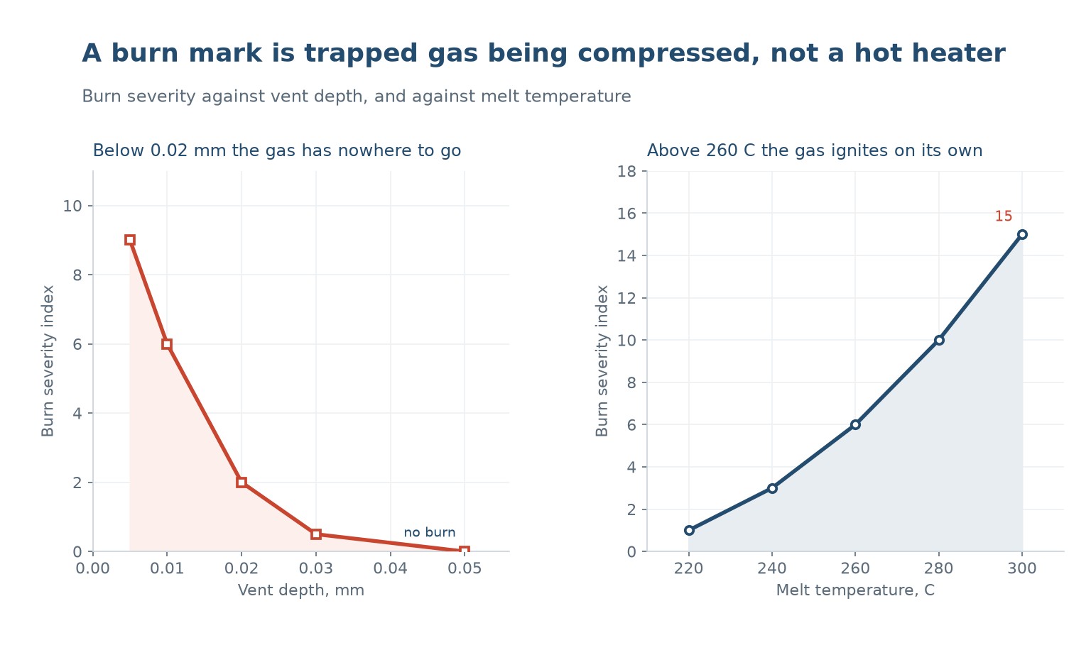
The effect on burn severity is dramatic and non-linear. At a vent depth of 0.005 mm the burn severity index is 9 out of 10, at 0.010 it is 6, at 0.020 it is 2, at 0.030 it is 0.5 and at 0.050 there is no burn at all. Most of the improvement happens between 0.01 and 0.02 mm, which is exactly the range where a vent that has been polished, painted over, or filled with a previous run's flash stops working.
This is why the first thing to check on a burning tool is not the process but the vent. A vent that was cut correctly when the tool was made can be closed by flash from a previous run, by a polish that rounded the edge, or by a release agent that has baked on. Cleaning it with a stone and a light pass with a 0.02 mm shim takes ten minutes and fixes a defect that process changes will not touch.
Melt temperature decides whether it ignites
The same trapped gas will not burn at every melt temperature. At 220 °C the burn severity index is 1, at 240 it is 3, at 260 it is 6, at 280 it is 10 and at 300 it is 15. Above about 260 °C the volatiles are hot enough to ignite with much less compression, so a marginal vent that was acceptable at 240 becomes a burning tool at 280.
This is the mechanism behind a very common production problem: a tool that ran fine for a year starts burning after a resin change to a higher-flow grade, which is processed hotter. Nothing about the tool changed, but the margin disappeared.
The interaction also explains why the same tool burns on one material and not another. Polypropylene generates more volatiles than polycarbonate at the same temperature, polyoxymethylene generates formaldehyde, and PVC generates hydrogen chloride, which is both a burn and a corrosion problem. A vent that is adequate for one is not necessarily adequate for another.
| Température de fusion | Burn severity | What it means | Action |
|---|---|---|---|
| 220 °C | 1 | A marginal vent is still adequate | None |
| 240 °C | 3 | A faint mark on the last part of the fill | Clean the vent |
| 260 °C | 6 | A clear mark; the margin is gone | Deepen or add a vent |
| 280 °C | 10 | Heavy charring at the flow end | Vent plus a lower melt temperature |
| 300 °C | 15 | Charring and a smell; the resin is degrading | The temperature is too high for the resin, not just for the vent |
Table 1 — Burn severity against melt temperature at a fixed marginal vent depth.
Injection speed cuts both ways
Faster injection raises the shear heating at the gate and compresses the trapped gas faster, so it tends to make a burn worse. Slower injection gives the gas more time to escape through a marginal vent, so it tends to make it better. That is the opposite of the advice for weld lines, where faster is better, and it is why a single 'injection speed' setting cannot be optimal for both defects.
The practical resolution is a velocity profile rather than a single speed. Fill fast through the bulk of the cavity, where weld line strength and surface finish matter, then slow down for the last 10 to 15 percent, where the gas is collecting. That gives the gas time to escape without losing the benefits of fast fill elsewhere.
A slower final fill also reduces the peak cavity pressure, which reduces flash. It is one of the few process changes that improves burn, flash and weld strength at the same time, and it is under-used because it requires a machine with a programmable velocity profile and an operator who will set it up.
Telling a burn from everything else
Dark marks on a moulded part have several possible causes and they are routinely confused. The location and the appearance separate them, and the separation matters because the fixes are completely different.
| Défaut | Where | Apparence | Cause |
|---|---|---|---|
| Burn mark | Last point to fill, or a blind pocket | Black or brown, often with a glossy edge | Trapped gas compressed and ignited |
| Colour streak | From the gate along the flow | A lighter or darker line, not black | Poor dispersion of masterbatch or a colour change |
| Black specks | Random, all over | Small dark dots | Degraded material in the barrel, a hot runner, or the regrind |
| Diesel shadow | Around a burn | A brown halo | Partial combustion products deposited on the surface |
| Gate blush | At the gate | A dull or frosty patch | Shear at the gate, not combustion |
Table 2 — Five dark-mark defects and how to tell them apart.
The black speck is the one that gets misdiagnosed most often. Specks that appear randomly across the part are not a venting problem; they are degraded material, and it comes from a hot runner with a dead spot, a barrel with a carbon layer, or regrind that has been through the machine too many times. Cleaning the vent will not fix them and purging the barrel will.
Venting that works
Good venting is designed, not added. A tool with vents only at the parting line will burn in any cavity where the last point to fill is not on the parting line, which is most cavities with a core or a deep feature.
- Vent at the last point to fill, which is a flow analysis question, not a guess.
- Vent depth 0.02 to 0.03 mm for most thermoplastics, 0.03 to 0.04 for polyolefins, and 0.01 to 0.015 for low-viscosity engineering resins.
- Vent land length 0.5 to 1.5 mm, then relieve to 0.3 mm so the vent does not clog.
- Vent ejector pins with a flat ground on the side, which is the cheapest way to vent a deep feature.
- Vent the runner as well as the cavity, because gas trapped in the runner arrives in the cavity.
- Use a porous steel insert in a blind pocket that cannot be vented conventionally.
The vent land length matters as much as the depth and is more often wrong. A vent that is 0.02 mm deep and 10 mm long has the same restriction as one that is 0.01 mm deep and 2.5 mm long, and it clogs far more readily. Short land, then a deep relief channel, is the pattern that works.
Diagnosing it in twenty minutes
- Look at where the mark is. If it is at the flow end, it is gas. If it is at the gate, it is shear. If it is random, it is contamination.
- Reduce the injection speed for the last part of the fill and see whether the mark lightens. If it does, it is gas.
- Drop the melt temperature by 20 °C and re-run. If the mark disappears, it was marginal venting plus a hot melt.
- Clean and check the vent at that location with a 0.02 mm shim. If the shim will not enter, the vent is closed.
- If the mark is still there with a clean vent, a cool melt and a slow final fill, cut a vent or add a porous insert, because the gas has nowhere to go.
The sequence is ordered so that the cheapest actions come first and the tool never gets touched until the process has been eliminated. In most plants it resolves at step 4, and the fix is a stone and ten minutes rather than a tool modification.
What causes burn marks in injection molding?
Trapped gas compressed to ignition temperature, usually at the last point to fill. It is the diesel effect, not a hot barrel or a hot heater.
How deep should a vent be?
0.02 to 0.03 mm for most thermoplastics, deeper for polyolefins and shallower for low-viscosity resins, with a short land and a deep relief behind it.
Why did my tool start burning after a resin change?
The new grade is probably processed hotter or generates more volatiles, so the margin the vent had is gone. Above a 260 °C melt, ignition needs much less compression.
Does faster injection make burns worse?
Usually yes, because it compresses the gas faster and adds shear heating. A velocity profile that fills fast and slows for the last 10 percent is the practical answer.
How do I tell a burn from black specks?
A burn is localised at the flow end. Black specks are random across the part and come from degraded material in the barrel, a hot runner dead spot, or regrind.
Can a burn be fixed without modifying the tool?
Often yes. Cleaning the vent, lowering the melt temperature and slowing the final fill will resolve a marginal case. If the vent is genuinely absent, the tool has to change.
A tool that burns at the end of the fill?
Send the part layout and the current vent detail. We will tell you where the last point to fill actually is, what vent depth it needs, and whether the process can get you there first.
Continue reading
- Injection Mold Venting: Where the Air Goes and Why Parts Burn
- Injection Molding Defects: 12 Problems, Their Causes and Fixes
- Flash in Injection Molding: Why More Clamp Force Is Not the Fix
- Hot Runner vs Cold Runner: Which Runner System to Specify
- Scientific Molding: The Five Studies and Why the Order Matters




 FR
 EN
 ES
 DE
 PT
 AR
 RU
 JA
 KO
 IT
 NL
 TR
 PL
 ID
