The problem
Symptom. A 4.2 mm self-tapping screw strips its PC/ABS boss at 0.9 N.m, below the 1.2 N.m assembly seating torque, because the pilot hole was opened to 3.8 mm and the boss OD cut to 8.0 mm.
What it costs. Bosses strip on the assembly line after other parts are fitted, so a hidden drawing fault turns into scrapped housings and a dispute over whether the screw, the hole or the torque driver is to blame.
This guide links boss geometry to strip torque, gives the OD/ID and pilot-hole figures for the drawing, and sets a strip-to-drive torque acceptance test before first article.
What a stripped boss looks like on the line
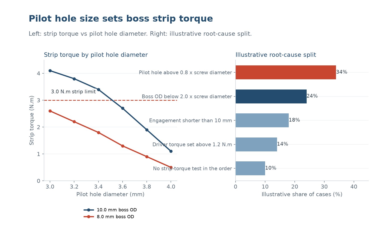
Strip torque scales with the wall around the screw. A 4.2 mm screw in a 3.4 mm hole and 10.0 mm boss OD holds 3.4 N.m; a 3.8 mm hole in an 8.0 mm OD falls to 0.9 N.m.
| Observed result | Most likely cause | First check on the order |
|---|---|---|
| Boss strips at 0.9 N.m, below 1.2 N.m seating | Pilot hole opened to 3.8 mm | Measure the pilot hole and boss OD on section |
| Strip torque scatters between drivers | Torque tool out of calibration | Check the driver certificate and setting |
| Only one cavity strips | Local core pin undersized | Log strip torque by cavity number |
| Screw spins but boss does not crack | Engagement under 10 mm | Measure thread engagement length |
Table 1 - Reading a stripped boss before changing the screw
Need a fixed price for this moulded part?
Send the 2D drawing, resin grade and annual volume. Our engineers return a DFM review, a material recommendation and a written quotation you can compare line by line.
Separate a geometry fault from the torque driver
Torque 10 fresh bosses to failure with a calibrated driver set to 1.2 N.m seating. A strip near 0.9 N.m with a clean, reamed 3.8 mm hole is geometry; scatter across drivers points at the torque tool.
A five-step diagnostic sequence
- Pull the drawing, the screw spec and the driver log.
Compare the quoted 3.4 mm hole and 10.0 mm OD with the 3.8 mm hole and 8.0 mm OD actually moulded. - Torque 10 fresh bosses to failure.
Use a calibrated driver at 1.2 N.m seating; a 0.9 N.m strip with a clean hole is geometry. - Section a stripped boss and measure the wall.
A 3.8 mm hole in an 8.0 mm OD leaves only 2.1 mm of wall against 3.3 mm on the drawing. - Check engagement length and core pins by cavity.
Confirm 10 mm engagement; one weak cavity usually means an undersized core pin. - Re-cut the hole and re-qualify the torque test.
Return to 3.4 mm and certify strip torque of at least 3.0 N.m on 10 bosses per cavity.
The chart below is a typical result from that measurement step. Use it to separate a design limit from a setting that can still be recovered.
Boss dimensions that belong on the drawing
Put the boss on the drawing: 10.0 mm OD, a 3.4 mm pilot hole for the 4.2 mm screw, 10 mm engagement, and a wall of 3.3 mm, giving an OD-to-screw ratio of 2.4 and a strip-to-drive ratio above 2.5.
| Paramètres | Typical target | What goes wrong outside it |
|---|---|---|
| Pilot hole for a 4.2 mm screw | 3.4 mm, about 0.8 x diameter | At 3.8 mm strip torque falls to 0.9 N.m |
| Boss OD / screw diameter | 2.4, about 10.0 mm OD | Below 2.0 the wall cannot hold the hoop load |
| Boss wall thickness | 3.3 mm at 10.0 mm OD | A 3.8 mm hole in 8.0 mm OD leaves 2.1 mm |
| Strip / drive torque ratio | Above 2.5 at 1.2 N.m seating | Below it the boss strips during assembly |
Table 2 - Boss and torque parameters for the part drawing
Hole, wall and engagement that set strip torque
A pilot hole above 0.85 times the screw diameter leaves too little thread engagement, and a boss OD below 2.0 times the screw diameter leaves too little hoop strength. Both cut strip torque below the 3.0 N.m floor.
| Decision | Effect on strip torque | Trade-off |
|---|---|---|
| Re-cut pilot hole to 3.4 mm | Restores 3.4 N.m strip torque | One-off core pin change |
| Raise boss OD from 8.0 to 10.0 mm | Adds 3.3 mm of wall | Larger boss may sink on the A-face |
| Lengthen engagement to 10 mm | More thread to carry load | Deeper boss, longer screw |
| Lower the driver to 1.2 N.m | Hides the strip, does not fix it | Joint may loosen in service |
Table 3 - Decisions ranked by tool-change cost
Define a strip-torque acceptance test
Agree acceptance before first article: a strip torque of at least 3.0 N.m, a strip-to-drive ratio above 2.5 at 1.2 N.m seating, measured on 10 bosses per cavity to failure with a calibrated driver.
Not sure whether the fault is in the tool or the process?
Send us the drawing, the process window and a few sample parts. We will tell you which change fixes the fault before you commit to a tool modification.
What to send us
- Part drawing with the affected dimension
- Current process settings
- Sample parts from a good and a bad batch
- Annual volume
Recovery actions ranked by tool-change cost
For a run already assembled, re-torque 10 retained bosses and record the failure mode. A 0.9 N.m strip means the pilot hole needs steel, not a softer driver; re-cut to the 3.4 mm hole and re-qualify.
Before you release this injection moulding job
- Pilot hole diameter of 3.4 mm for the 4.2 mm screw is dimensioned on the drawing
- Boss OD of 10.0 mm and a 3.3 mm wall are specified with an OD-to-screw ratio of 2.4
- A strip torque of at least 3.0 N.m and a strip-to-drive ratio above 2.5 are agreed
- The 1.2 N.m seating torque and a calibrated driver are named in the assembly method
- First-article strip torque is reported on 10 bosses per cavity to failure
Attach this list to the RFQ. Most moulding faults are decided at the drawing stage.
Why does the boss strip below the assembly torque?
A 3.8 mm pilot hole in an 8.0 mm OD boss leaves only 2.1 mm of wall, so strip torque is 0.9 N.m against a 1.2 N.m seating torque.
Is the screw or the hole to blame?
Usually the hole. A 4.2 mm screw in a 3.4 mm hole and 10.0 mm OD holds 3.4 N.m; the same screw strips at 0.9 N.m once the hole is opened.
What OD-to-screw ratio should we use?
About 2.4, so a 10.0 mm OD for a 4.2 mm screw, giving a 3.3 mm wall. Below 2.0 the boss lacks hoop strength.
Can a lower driver setting fix it?
No. It hides the strip and leaves the joint loose. Set the 1.2 N.m seating torque and require strip torque above 3.0 N.m instead.
How many bosses should we test?
Torque 10 bosses per cavity to failure with a calibrated driver, and report strip torque and failure mode, not just pass or fail.
Who owns a stripped batch?
Put it in the order. Name the hole, OD, engagement and a 3.0 N.m strip limit so the batch is judged by a torque record.
Get a mouldable part and a fixed quotation
Send us the part file and the failure history. Our engineers will return a DFM review, a material recommendation and a fixed quotation with a defined first-article acceptance test.
To get an accurate quote, send:
- 3D file or 2D part drawing
- Resin grade and any regrind limit
- Annual volume and target unit price
- The failed sample or defect photos
Request a DFM review and quote
Why buyers work with Uplastech
ISO 9001, ISO 14001 and ISO 45001 certified. Founded in 2016, with injection moulding lines in Shanghai and an extrusion plant in Jiangsu. Moulding machines from 90T to 1100T and a maximum shot weight of 5100 g. Samples and a written quotation are available on request.

 FR
 EN
 ES
 DE
 PT
 AR
 RU
 JA
 KO
 IT
 NL
 TR
 PL
 ID