
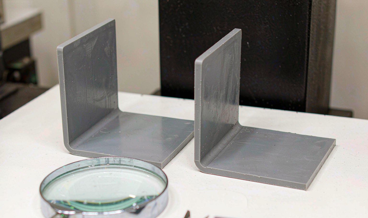
What a stress concentration actually is
Stress concentration is the ratio of the peak stress at a feature to the nominal stress in the section. A factor of 3.4 means the material at the corner sees 3.4 times the stress you calculated for the section. It is a purely geometric effect: it does not depend on the material, only on the shape.
The factor is driven by how abruptly the load path has to turn. A sharp internal corner forces the stress lines to converge into a point, and the smaller the radius relative to the wall, the tighter that convergence.
The useful parameter is r/t, the radius divided by the wall thickness. Not the radius on its own: a 0.5 mm radius is generous on a 1 mm wall and sharp on a 5 mm wall. Design rules that quote a radius in millimetres without reference to the wall are quoting half a rule.
The curve is steep at the small end and flat at the large end. At r/t of 0.02, Kt is 3.42. At 0.05 it is 2.62, at 0.1 it is 2.22, at 0.2 it is 1.62, at 0.3 it is 1.44, at 0.5 it is 1.28 and at 1.2 it is 1.14. Most of the available improvement is gone by r/t of 0.3.

What it does to fatigue life
Stress concentration matters most in fatigue, because fatigue life depends on the peak stress, not the average. A part with Kt of 3.42 and a nominal stress of 20 MPa sees 68 MPa at the corner, which for an unfilled PA66 at 10 million cycles is past the endurance limit.
The chart on the right is the same bracket, the same load, six different corner radii. At 0.1 mm the part lasts about 8,000 cycles. At 0.3 mm it is 26,000. At 0.5 mm, 62,000. At 1.0 mm, 180,000. At 2.0 mm, 420,000. At 4.0 mm, 610,000.
From 0.1 to 0.5 mm, a change of 0.4 mm on a drawing, life goes up by nearly eight times. That is the single best return on any dimension on the part. It costs nothing in material, nothing in cycle time, and it is decided once, in the tool.
The reason the gain is so large is that fatigue life is roughly a power law in stress. A 30 percent drop in peak stress can be a five to ten times increase in cycles, depending on where you are on the S-N curve. The Kt curve and the S-N curve multiply.
Where the radii have to go
The internal corner where a rib meets a wall is the classic. It is also the one most often drawn as a sharp corner because the CAD default is sharp and nobody changed it. Every rib root on a part is a stress riser, and a part with twenty ribs has twenty of them.
Boss roots are the second. A boss is a cylinder standing on a wall, and the junction is a re-entrant corner all the way round. The rule of thumb is a fillet at least a quarter of the boss diameter, and a generous draft on the boss so the fillet has room.
The third is any step change in section. A wall that goes from 2 mm to 3 mm in a sharp step has a stress concentration at the step, and it also has a moulding problem: the thick section sinks and the thin section fills late. A taper or a radius solves both.
The fourth is the corner of a pocket or a window. A rectangular window with sharp corners in a moulded panel will crack from the corners under any bending load. A corner radius of at least half the wall thickness is the minimum, and a full radius is better.
What a radius costs, and what it costs to skip
A larger radius costs nothing in material. It adds a small amount of material at the corner, which is usually in the wrong place for sink but in the right place for strength. It can cost cycle time if the thicker corner needs longer to cool, and that is the only real penalty.
It costs tool work if it is added late. A tool that has been cut with a sharp corner can be re-machined with a radius, but the corner has to be picked up, the electrode remade, and the tool re-polished. That is a day of tool time and a production interruption, against a change that would have cost nothing at the design stage.
Skipping it costs warranty. A part that cracks at a rib root in service does not fail at the design load; it fails at a fraction of it, after a number of cycles nobody predicted. The diagnosis is always the same, and it is always visible on the drawing if anyone looks.
There is one case where a sharp corner is correct: a feature that has to shear at a defined load, such as a breakaway tab. There the stress concentration is the function. Everywhere else it is an accident.
How to specify it
Specify r/t rather than a radius in millimetres, or specify both. A note that says "internal radii 0.5 mm min" is meaningless on a part with a 4 mm wall, where 0.5 mm is r/t of 0.125 and Kt of 2.1. The same note on a 1 mm wall gives r/t of 0.5 and Kt of 1.28.
Give the radii at the features that matter, not a blanket note. The rib roots, the boss roots and the window corners are the three that carry load. A general note that covers the whole part is usually ignored at exactly those three.
Check the tool drawing against the part drawing. Toolmakers work from the tool drawing, and a radius that exists on the part drawing but not on the tool drawing will not be in the steel. This is the most common way a good design arrives as a sharp corner.
| Feature | Minimum radius | Kt at the minimum | Better |
|---|---|---|---|
| Rib root | 0.25 x wall | 1.44 | 0.5 x wall, Kt 1.28 |
| Boss root | 0.25 x boss diameter | 1.44 | 0.3 x diameter |
| Wall step | 0.5 x thinner wall | 1.28 | Taper over 3 x the step |
| Window corner | 0.5 x wall | 1.28 | Full radius if the shape allows |
| Sharp as designed | n/a | 3.42 | Only for breakaway features |
Table 1 — Minimum radii by feature, and what a larger one buys
A check you can do in five minutes
Open the part drawing and count the internal corners. Then, for each one, divide the radius by the local wall thickness. Anything below 0.2 is a stress riser that will show up in fatigue, and anything at zero is a crack waiting for a load.
The corners that matter are the ones at the ends of the load path. On a bracket, that is the corner where the web meets the flange. On a housing, it is the boss roots and the rib roots. On a panel, it is the window corners. You do not need to fix every corner on the part, only the ones carrying load.
Then check whether the tool drawing has them. If the part drawing says 0.5 mm and the tool drawing says sharp, the part will be sharp, and the argument about who is responsible happens after the parts crack.
| Symptom in service | Corner to look at | Typical Kt found |
|---|---|---|
| Crack at a rib root | Rib to wall junction | 2.5 to 3.4 |
| Boss pulls out of the wall | Boss to wall junction | 2.0 to 3.0 |
| Crack from a window corner | Window corner radius | 2.2 to 3.4 |
| Part breaks at a step | Wall thickness step | 1.8 to 2.6 |
| Crack runs along a weld line | Gate position, not a radius | Material dependent |
Table 2 — Matching a field failure to the corner that caused it
What radius should an internal corner have?
At least 0.25 times the local wall thickness, and 0.5 is better. At r/t of 0.25 the stress concentration is about 1.44; at 0.5 it is 1.28; a sharp corner is 3.42.
Why does a small radius matter so much if the part is not heavily loaded?
Because fatigue depends on peak stress, not average. A Kt of 3.4 turns a 20 MPa nominal stress into 68 MPa at the corner, which is enough to start a crack in an unfilled nylon at high cycle counts.
Does a bigger radius cost anything?
A little material at the corner, and possibly a little cycle time for cooling. It costs nothing at the design stage and a day of tool time if it is added after the tool is cut.
Should I specify a radius in millimetres or as a ratio?
As a ratio of the wall thickness, or both. A 0.5 mm radius is generous on a 1 mm wall and sharp on a 4 mm wall, so a millimetre value alone does not define the stress concentration.
Are there cases where a sharp corner is correct?
Yes, where the feature is meant to shear at a defined load, such as a breakaway tab. Everywhere else a sharp corner is an unintended stress riser.
The part drawing has radii but the parts are sharp. Why?
The tool was cut from the tool drawing, and the radius was not carried across. Check the tool drawing against the part drawing at the rib roots, boss roots and window corners.
Part cracking at a corner?
Send the drawing and a photo of the failure. We will check the r/t at the corners that carry load and tell you which radius to change and what it buys in fatigue life.




 EN
 ES
 FR
 DE
 PT
 AR
 RU
 JA
 KO
 IT
 NL
 TR
 PL
 ID
