The problem
Symptom. A deep ABS tray sticks in the cavity and bows at the ejector pins, with a peak ejection force trace of 14 kN against the 8 kN ceiling on a tool cut at only 0.5 degree draft.
What it costs. Sticking parts deform at ejection or need an operator to free them, so the cycle is unstable, scrap rises and the dispute centres on whether the tool polish or the packing pressure is to blame.
This guide reads the ejection force trace, sets draft, polish direction and a force ceiling for the drawing, and defines an ejection acceptance test before first article.
What a sticking part looks like at ejection
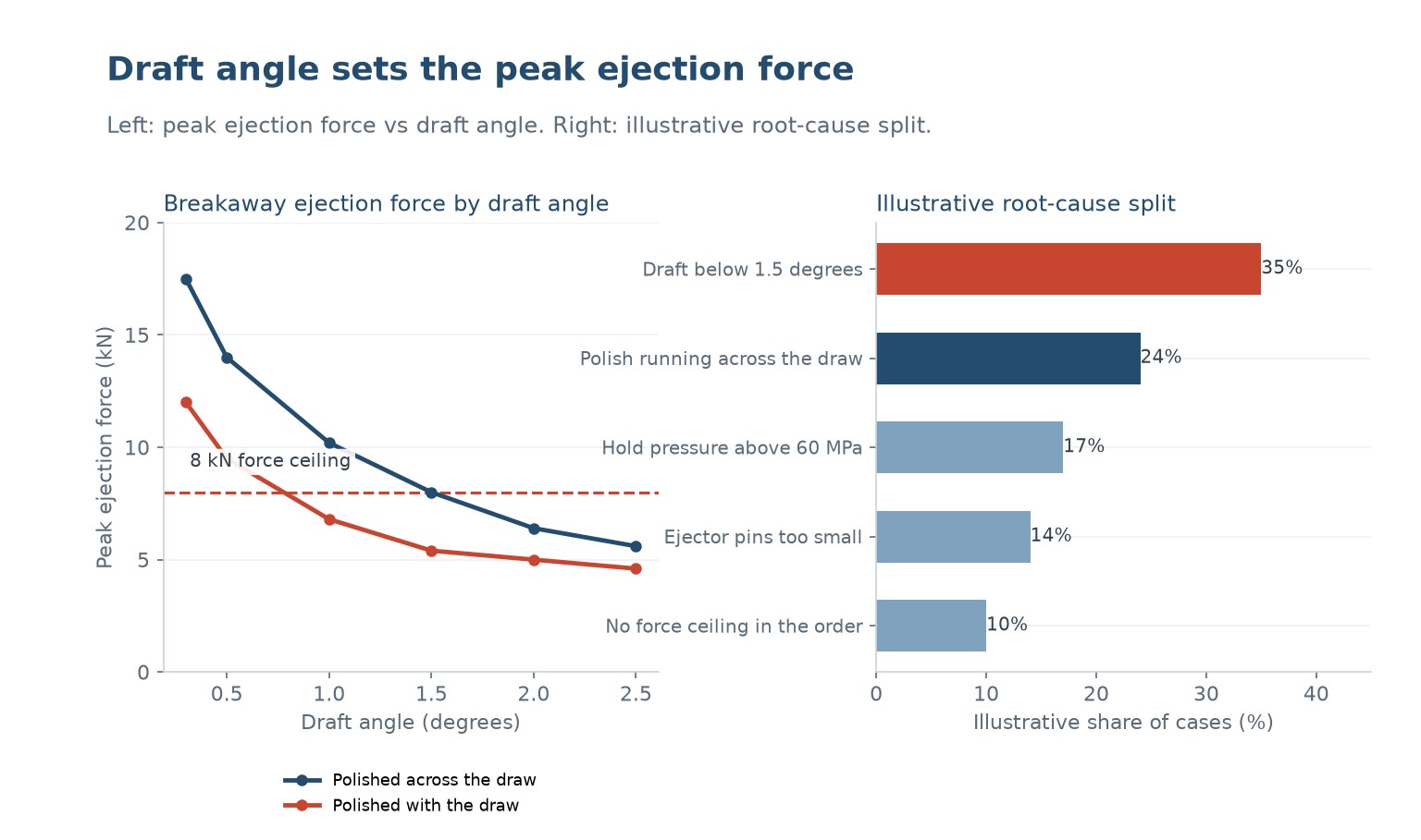
A sticking part is a force problem, not a release-agent problem. A 0.5 degree draft with cross-draw polish on a deep ABS tray peaks at 14 kN on ejection, 75 % above an 8 kN ceiling, and bows at the pins.
| Observed result | Most likely cause | First check on the line |
|---|---|---|
| Ejection peak of 14 kN, parts bow | 0.5 degree draft, cross polish | Log breakaway force over 10 shots |
| Peak falls when hold pressure is trimmed | Over-packing at 90 MPa | Compare 90 and 60 MPa traces |
| One cavity sticks, others release | Local polish or a worn core | Log the peak by cavity number |
| Force normal but part deforms | Ejector pins too small | Check pin area against the yield stress |
Table 1 - Reading a sticking part before re-polishing
Need a fixed price for this moulded part?
Send the 2D drawing, resin grade and annual volume. Our engineers return a DFM review, a material recommendation and a written quotation you can compare line by line.
Separate a draft fault from over-packing
Fit a load cell on the ejector plate and record the breakaway peak over 10 shots per cavity. A 14 kN peak that falls as hold pressure is trimmed is packing; a constant peak follows draft or polish.
A five-step diagnostic sequence
- Fit a load cell and record the breakaway peak.
A 14 kN ejection peak against an 8 kN ceiling is 75 % over and explains the bowed parts. - Compare traces at 90 and 60 MPa hold pressure.
A peak that falls with pressure is packing; a constant 14 kN peak is draft or polish. - Measure draft and read the polish direction.
Confirm at least 1.5 degrees and SPI B1 polish running with the draw, not across it. - Check ejector pin area and cavity balance.
Small pins deform the part even at 8 kN; a single high cavity points at a worn core. - Re-qualify against the 8 kN ceiling.
Log 10 consecutive shots per cavity and confirm no ejector witness after 48 h.
The chart below is a typical result from that measurement step. Use it to separate a design limit from a setting that can still be recovered.
Draft and polish details for the drawing
Put the release geometry on the drawing: at least 1.5 degrees draft, polish to SPI B1 in the draw direction only, a maximum peak ejection force of 8 kN, and ejector pins sized to keep stress below the yield.
| Parámetro | Typical target | What goes wrong outside it |
|---|---|---|
| Minimum draft angle | 1.5 degrees, 2.0 on deep trays | At 0.5 degrees the peak reaches 14 kN |
| Polish direction and finish | SPI B1, in the draw direction | Cross-draw polish raises friction |
| Peak ejection force ceiling | At most 8 kN per cavity | A 14 kN peak bows the part |
| Hold pressure | 60 MPa | At 90 MPa an extra 1.5 kN of grip |
Table 2 - Ejection parameters for the part drawing
Geometry and pressure that raise ejection force
Raising draft from 0.5 to 2.0 degrees and polishing along the draw cut the breakaway peak from 14 to about 5 kN. Dropping hold pressure from 90 to 60 MPa removes another 1.5 kN without touching steel.
| Decision | Effect on ejection force | Trade-off |
|---|---|---|
| Increase draft 0.5 to 2.0 degrees | Peak falls 14 to about 5 kN | Tool change, re-qualify dimensions |
| Polish in the draw direction | Removes cross-draw friction | A polish pass on every core |
| Reduce hold pressure 90 to 60 MPa | Saves about 1.5 kN | Risk of sink over thick ribs |
| Add more ejector pins | Lowers stress on each pin | More witness marks on the B-face |
Table 3 - Decisions ranked by tool-change cost
Agree a peak-force acceptance test
Agree acceptance before first article: a peak ejection force at most 8 kN on 10 consecutive shots per cavity, 1.5 degrees minimum draft, draw-direction polish, and no ejector witness after 48 h at 23 C / 50 % RH.
Not sure whether the fault is in the tool or the process?
Send us the drawing, the process window and a few sample parts. We will tell you which change fixes the fault before you commit to a tool modification.
What to send us
- Part drawing with the affected dimension
- Current process settings
- Sample parts from a good and a bad batch
- Annual volume
Recovery actions ranked by tool-change cost
For a sticking run, drop hold pressure from 90 to 60 MPa and log the peak for 10 shots. A same-shift fall to 8 kN clears the batch; a constant 14 kN needs re-polish or a draft change in the tool.
Before you release this injection moulding job
- A minimum draft of 1.5 degrees, or 2.0 on deep trays, is dimensioned on the drawing
- Polish direction in the draw and an SPI B1 finish are specified for every core
- A peak ejection force ceiling of 8 kN is agreed for each cavity
- An ejector-force load cell and a 10-shot trace are written into the control plan
- First-article approval reports the breakaway peak and checks for ejector witness after 48 h
Attach this list to the RFQ. Most moulding faults are decided at the drawing stage.
Why does the part stick and bow at the pins?
A 0.5 degree draft with cross-draw polish gives a 14 kN breakaway peak, 75 % above the 8 kN ceiling, so the ejector pushes harder than the tray can take.
Is it the tool or the packing pressure?
Trim hold from 90 to 60 MPa and watch the trace. A peak that falls is packing; a constant 14 kN peak is draft or polish and needs steel.
How much draft is enough?
At least 1.5 degrees, and 2.0 on a deep tray. Raising draft from 0.5 to 2.0 degrees cuts the breakaway peak from 14 to about 5 kN.
Does polish direction really matter?
Yes. Polish must run with the draw. Cross-draw scratches act like tiny undercuts, holding the part even at a correct draft angle.
What acceptance test should we specify?
A peak ejection force at most 8 kN on 10 consecutive shots per cavity, with an ejector-force trace and no witness mark after 48 h at 23 C / 50 % RH.
Who owns a deformed batch?
Put it in the order. Name the draft, the polish direction and the 8 kN ceiling so a sticking part is judged by a force trace, not an opinion.
Get a mouldable part and a fixed quotation
Send us the part file and the failure history. Our engineers will return a DFM review, a material recommendation and a fixed quotation with a defined first-article acceptance test.
To get an accurate quote, send:
- 3D file or 2D part drawing
- Resin grade and any regrind limit
- Annual volume and target unit price
- The failed sample or defect photos
Request a DFM review and quote
Why buyers work with Uplastech
ISO 9001, ISO 14001 and ISO 45001 certified. Founded in 2016, with injection moulding lines in Shanghai and an extrusion plant in Jiangsu. Moulding machines from 90T to 1100T and a maximum shot weight of 5100 g. Samples and a written quotation are available on request.

 ES
 EN
 FR
 DE
 PT
 AR
 RU
 JA
 KO
 IT
 NL
 TR
 PL
 ID