

What actually limits output
An extruder is a pump, and like any pump it has a curve. At low screw speed the output rises almost linearly, because each turn moves a fixed volume forward. At higher speed the curve bends over and eventually flattens, and the flattening is not a mechanical limit of the motor or the gearbox in most cases.
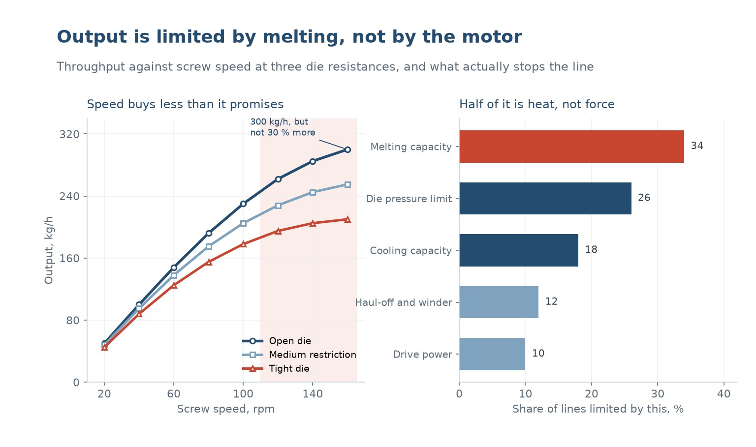
The first limit is melting. The polymer has to be brought from solid to melt within the length of the screw, and the heat comes from the barrel heaters and from the shear the screw generates. At high speed the material passes through the compression section faster, so it has less time to absorb heat, and unmelded material arrives at the metering section and blocks the flow.
The second limit is die pressure. A die with a small opening or a long land resists the flow, and the pressure that has to be generated to push material through it comes from the screw. As pressure rises, the backflow over the flight increases, and the net output falls even though the screw is turning faster.
The third limit is cooling. A profile that is extruded at 300 kg/h has to be cooled at 300 kg/h, and the water bath or the air ring has a finite capacity. A line that is limited by cooling will show a profile that is still soft at the haul-off, and no amount of screw speed will fix it.
Melting capacity, not drive power
On most single screw lines the drive is sized generously, and the motor is rarely the limit. A 90 mm machine with a 75 kW motor can turn at 150 rpm all day without reaching its rated current, while the output has already flattened at 110 rpm. The current meter tells the story: if it is not near the rated value, the drive is not the constraint.
Melting capacity is a function of screw geometry, barrel temperature and material. A screw with a long compression section and a barrier flight melts more per turn than a simple single stage screw. A barrel profile that is hotter in the compression zone melts faster. A material with a high thermal conductivity melts faster than one with a low one.
The symptom of a melting limit is unmelted material in the extrudate, a fluctuating die pressure and a melt temperature that drops as the speed rises. That last one is counter-intuitive: more speed should mean more shear heating and a hotter melt, and a falling melt temperature means the material is not being melted at all, it is arriving as solid.
The fixes are a hotter barrel profile in the compression zone, a screw with a longer melting section, or a grooved feed throat that increases the feed rate and the pressure in the feed zone. A grooved throat is the most effective single change and is often retrofittable.
Die resistance and back pressure
The die is a restriction, and the pressure required to push material through it depends on its geometry and on the melt viscosity. A tight die raises the pressure, and a raised pressure increases the backflow over the screw flight, which reduces the net output. The effect is stronger on a worn screw, because the flight clearance is larger and the backflow is easier.
The chart on the left shows the same screw running against three dies. At 40 rpm the three outputs are within 12 percent of each other, because the pressure is low and the backflow is small. At 160 rpm the open die gives 300 kg/h, the medium die 255 and the tight die 210. The gap widens with speed, which is the signature of a pressure limit.
The practical consequence is that a die change can change the output of a line without touching the screw. A die that is 20 percent more restrictive can cost 15 percent of the output at high speed and almost nothing at low speed, which is why a line that ran well with one profile can struggle with another.
Screen packs are part of the die resistance and are the part that changes with time. A clean screen adds little; a loaded screen can add 30 bar and cost 10 percent of the output. A line whose output falls over a shift is usually showing a screen building up, not a screw wearing out.
The output curve flattens
The shape of the curve matters more than any single number on it. In the linear region, a 10 percent increase in screw speed buys a 10 percent increase in output. In the flattened region, the same 10 percent buys almost nothing, and the extra energy goes into shear heating and wear instead of product.
The knee of the curve is where the line should normally run. Running below the knee leaves capacity unused; running above it costs energy, wear and melt quality for very little output. On the chart the knee is around 110 to 120 rpm, and the last 40 rpm buys about 15 percent more output for 30 percent more screw wear.
That trade is worth understanding because it is invisible on a production report. A line running at 160 rpm looks more productive than one running at 120, and it is, by 15 percent. It also consumes more energy per kilogram, wears faster and produces a less stable melt, and those costs appear in maintenance and quality rather than in the output figure.
The right operating point is therefore not the maximum. It is the point where the marginal kilogram costs less than it earns, and on most lines that is 70 to 85 percent of the maximum screw speed.
Downstream capacity is the limit that gets discovered last, because it does not show up on the extruder at all. A water bath that is 4 m long can cool a certain mass per hour; beyond that the profile leaves the bath still warm and deforms at the haul-off. The extruder will happily run faster and produce scrap.
The calculation is straightforward. The heat to be removed per kilogram is the enthalpy difference between the melt and the finished profile, which for a polyolefin is roughly 400 to 500 kJ/kg. A 4 m bath with a 200 litre per minute water flow and a 10 C rise removes about 140 kW, which corresponds to about 1,000 kg/h. That sounds generous until the line is a 90 mm machine running at 400 kg/h with a bath that is already at its limit.
Air cooling is worse, because air carries far less heat per unit volume. A profile cooled only by air needs a much longer distance, and the length is set by the line layout, which is fixed. That is why air cooled lines are usually limited to thin profiles and low outputs.
The check is a temperature measurement at the haul-off. A profile that is above its heat deflection temperature at the haul-off is being pulled out of shape, and the output has to come down or the cooling has to be improved. Improving the cooling, with spray nozzles or a longer bath, is usually cheaper than accepting the lower output.
Measuring where you are
The first measurement is the output curve itself: run the line at five screw speeds, weigh the output over five minutes at each, and plot it. That takes an hour and shows immediately whether the line is in the linear region or past the knee.
The second is the die pressure at each speed. A pressure that rises steeply with speed indicates a die limit; a pressure that stays flat while the output flattens indicates a melting limit. The two limits look identical on the output curve and completely different on the pressure gauge.
The third is the melt temperature at each speed. A falling melt temperature with rising speed is the signature of incomplete melting, and it is the most reliable single indicator of a melting limit. A rising melt temperature indicates shear heating and suggests the line is already past its efficient point.
| Symptom | Likely limit | First check |
|---|---|---|
| Output flat, pressure flat, melt temperature falling | Melting capacity | Barrel profile in the compression zone |
| Output flat, pressure rising steeply | Die resistance | Screen pack and die land |
| Output flat, motor current near rated | Drive power | Gearbox ratio and screw speed |
| Profile soft at the haul-off | Cooling capacity | Bath length and water flow |
| Output falls over a shift | Screen building up | Pressure trend against time |
| Output low from new, all speeds | Screw design for the material | Compression ratio and flight depth |
Table 1 — Reading the symptom to find the limit
Getting more from the line you have
The cheapest gain is usually the screen pack and the die. A clean screen, a die with a slightly shorter land and a properly sized breaker plate can recover 5 to 10 percent of output at no capital cost. It is the first thing to check and the most often neglected.
The second is the barrel profile. Raising the compression zone temperature by 10 to 15 C increases the melting rate and moves the knee of the curve to the right. The limit is the material: too hot and the melt degrades, or the cooling load downstream rises and the gain is lost.
The third is the feed throat. A grooved feed throat increases the feed rate and the pressure in the feed zone, which raises the melting rate and the output. It is a screw and barrel modification rather than a setting, and it is the single most effective change on a line that is melting limited.
| Change | Typical gain | Coste | Riesgo |
|---|---|---|---|
| Clean screen and die | 5 to 10 % | Almost none | None |
| Raise compression zone temperature | 5 to 8 % | Energy only | Degradation if too hot |
| Grooved feed throat | 15 to 25 % | Moderate, a barrel change | Higher wear on the feed section |
| Longer cooling bath | Removes the downstream limit | Moderate, floor space | Layout change |
| Barrier screw | 20 to 30 % | A new screw | Needs a matched barrel |
| Larger machine | Depends on the step | Alta | A new line |
Table 2 — Options in order of cost against gain
The order in the table is the order in which the options should be considered. The first two cost almost nothing and are usually enough to move a line from the flat part of the curve back to the knee. The last two are capital projects and should only be reached after the first four have been tried.
Why does my output stop rising when I increase screw speed?
The line has reached a limit other than screw speed. The most common is melting capacity: the material is not fully melted by the time it reaches the metering section, so more speed just pushes unmelted material. Check the melt temperature; if it falls as speed rises, it is melting.
Is a bigger motor the answer to low output?
Almost never. The motor is sized for the maximum torque the screw needs, and on most lines the current at maximum output is well below rated. If the current is near rated, the drive is the limit; if it is not, look at melting, die pressure or cooling.
How do I know if the die is limiting my output?
Plot die pressure against screw speed. If the pressure rises steeply as the output flattens, the die is the limit. If the pressure stays flat, the limit is upstream. A quick test is to remove the screen pack and see whether the output recovers.
What is a grooved feed throat and does it help?
A section of the barrel behind the feed zone with axial grooves that increase friction and prevent the material from rotating with the screw. It raises the feed rate and the pressure, which raises the melting rate. It typically gains 15 to 25 percent on a melting limited line.
Why does output fall during a shift?
The screen pack is loading up, which raises the die pressure and increases the backflow over the flight. A clean screen restores the output. If the fall is gradual and repeatable, it is the screen; if it is sudden, look at the material or the feeder.
Should I run at maximum screw speed?
No. Above the knee of the curve the extra output is small and the cost in energy, wear and melt stability is large. Most lines are most efficient at 70 to 85 percent of maximum screw speed, and that is where they should be set.
Line not reaching its rated output?
Send the screw diameter, the polymer, the die and the output you are getting. We will tell you which limit you are hitting and what it would take to move it.




 ES
 EN
 FR
 DE
 PT
 AR
 RU
 JA
 KO
 IT
 NL
 TR
 PL
 ID
