Wall thickness is the cycle time
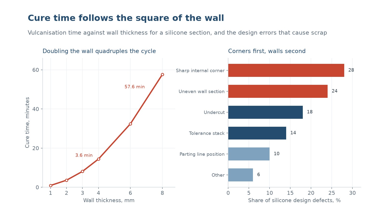
In injection moulding, wall thickness affects cycle time roughly linearly. In silicone it affects it roughly quadratically, because the material cures by heat transfer through the section and the heat has to conduct from the outside in. Double the wall and the centre takes four times as long to reach cure temperature.
The chart on the left shows the consequence with a typical silicone compound. A 1 mm section cures in about 0.9 minutes, 2 mm in 3.6, 3 mm in 8.1, 4 mm in 14.4, 6 mm in 32.4 and 8 mm in 57.6. A part with an 8 mm section runs at 57.6 minutes, which for most products is not a commercial cycle.
The design rule that follows is to keep sections uniform and thin, and to avoid thick bosses and ribs entirely. Where a thick section is needed for strength, the alternative is a different geometry: a hollow sleeve instead of a solid block, a ribbed web instead of a solid wall, or a metal insert encapsulated in a thin wall rather than a thick one.
Uneven sections are worse than thick ones, because the thin part cures first and the thick part is still soft when the mould opens. The result is a part that tears at the transition, or a surface that is over-cured and brittle next to one that is under-cured and tacky. A gradual transition over at least three times the thickness difference is the standard remedy.
Corners are where parts tear
Sharp internal corners are the largest single cause of silicone design defects at 28 percent, and the mechanism is a stress concentration. A sharp internal corner in a flexible material concentrates strain by a factor of three or more, and silicone has modest tear strength, so the corner is where a tear starts when the part is demoulded or stretched over a spigot in service.
The rule is a minimum internal radius of half the wall thickness, and one times the wall thickness where the part will be flexed. That is a generous radius by the standards of rigid plastics, and it is not optional: a silicone part with a 0.2 mm radius on a 2 mm wall will tear in the first hundred cycles of a flexing application.
External corners matter less for strength and more for appearance and moulding. A sharp external edge on a compression moulded part fills poorly because the material has to flow into a thin edge, and the result is a rounded, slightly ragged corner that looks like a defect. A 0.5 mm radius makes the edge crisp and the flow easier.
Undercuts need a split tool or a compliant demould
Silicone is flexible, which means a modest undercut can be stripped off a rigid core rather than requiring a split tool. That is a genuine advantage over rigid plastics and it is widely used for seals, grommets and boots. The limit is the strain the material can take at the undercut, and it is lower than most designers assume.
A practical guide is that an undercut up to about 5 percent of the part diameter can be stripped from a rigid core, provided the material is 50 Shore A or softer and the undercut has a lead-in chamfer. Beyond that, the part tears or the core needs a split, and a split core doubles the tool cost and adds a parting line on a sealing surface.
Undercuts account for 18 percent of design defects, and most of them are avoidable by changing the demould direction. A part that is designed to be pulled off a core in one direction, with the undercut on the outside where a stripper plate can reach it, is a cheaper part than one that needs a split.
| Merkmal | Minimum | Preferred | Warum |
|---|---|---|---|
| Wall thickness | 0.8 mm | 1.5 to 3 mm | Below 0.8 mm the material will not flow; above 4 mm the cycle explodes |
| Internal corner radius | 0.5 x wall | 1.0 x wall | Tear initiation at demoulding and in flexing |
| External corner radius | 0.3 mm | 0.5 mm | Fill and appearance |
| Section transition | 2 x difference | 3 x difference | Under-cure at the thick end |
| Undercut, strippable | 3 percent of diameter | 5 percent, with a chamfer | Tear on demoulding |
| Draft angle | 1 degree | 3 degrees | Release and surface marking |
Table 1 — The working design rules for a moulded silicone part.
Tolerance is a different animal
Silicone shrinks between 1.5 and 4 percent depending on the compound and the cure, and the shrinkage is not uniform: it depends on section thickness, on mould temperature and on the direction of flow. A tolerance of plus or minus 0.1 mm on a 20 mm silicone part is achievable but it is at the edge of what the process can hold repeatedly.
The practical tolerance for a moulded silicone part is plus or minus 0.25 mm for dimensions under 25 mm, plus or minus 0.5 mm up to 100 mm, and a percentage above that. Anything tighter needs either a post-cure to stabilise shrinkage, a fixture to hold the part during measurement, or a secondary machining operation that is usually more expensive than the tolerance is worth.
Tolerance stack is 14 percent of design defects, and it usually appears at an assembly interface where a silicone part has to fit a rigid one. The mistake is to apply the rigid part's tolerance philosophy to the flexible one: a silicone seal does not need a tight dimensional tolerance, it needs the right compression and the right groove volume. Specifying the compression rather than the dimension is both cheaper and more reliable.
Design for the process you will use
Silicone parts are made by compression moulding, transfer moulding, injection moulding or LSR injection. Each has a different relationship with the design, and the same drawing can be cheap in one and impossible in another.
Compression moulding is the cheapest tooling and the slowest cycle, and it handles thick sections and low volumes. Transfer moulding adds a pot and a sprue, which improves dimensional consistency and allows more complex parts. Injection moulding of high consistency silicone needs a much more expensive tool but runs fast cycles, and LSR injection is faster still with a liquid material and a cooled runner.
The design implication is the parting line and the flash. A compression moulded part has flash on the parting line that has to be deflashed by hand or by cryogenic tumbling, and a sealing surface should never be on that line. An injection moulded part has flash at the same place but much less of it, which is why injection moulding is preferred for parts with a critical sealing face.
The second implication is the insert. A metal insert encapsulated in silicone has to be held on a pin during moulding, and the pin leaves a witness mark. Designing the mark onto a non-sealing, non-visible face costs nothing at the drawing stage and is expensive to fix later.
| Prozess | Tool cost | Cycle | Am besten für |
|---|---|---|---|
| Compression moulding | Lowest | Slowest | Thick sections, low volume, simple shapes |
| Transfer moulding | Niedrig | Mäßig | Complex shapes, better dimensional consistency |
| Injection moulding, HCR | Hoch | Schnell | High volume, thin walls, critical sealing faces |
| LSR injection | Highest | Fastest | Very high volume, tiny parts, tight tolerance |
Table 2 — Silicone processes and what each one is suited to.
A short checklist before release
Before a silicone drawing goes to tooling, six things should be checked. Is every section within 0.8 to 4 mm, and as uniform as the function allows. Is every internal corner at least half the wall thickness in radius. Is every section transition at least three times the thickness difference. Is every undercut either strippable or on a split. Is the sealing surface away from the parting line. And is the tolerance expressed as a compression or a fit rather than a rigid dimension.
A seventh check is worth adding for parts that will be assembled: what happens when the part is stretched or compressed during installation. A seal that is stretched 10 percent to fit a groove will be thinner than its drawing, and its compression will be lower than calculated. Designing for the installed state rather than the free state is the difference between a seal that works and one that weeps.
The cost of these checks is an hour of drawing review. The cost of missing one is a tool that has to be modified, which is four to eight weeks and a new tooling invoice, on a part whose material cost is often less than the tool change.
What is the ideal wall thickness for a silicone part?
Between 1.5 and 3 mm for most parts. Below 0.8 mm the material will not flow reliably; above 4 mm the cure time rises steeply, because cure follows the square of the thickness and an 8 mm section takes about 58 minutes against 14 for 4 mm.
Why does doubling the wall quadruple the cure time?
Because silicone cures by heat conducting into the section from the mould surface. The heat has to travel twice as far and heat four times the volume, so the centre of a section twice as thick takes roughly four times as long to reach cure temperature.
What radius does an internal corner need?
At least half the wall thickness, and one times the wall thickness for a part that will flex in service. Silicone has modest tear strength, and a sharp internal corner concentrates strain by a factor of three or more, which is where tears start.
Can silicone parts have undercuts?
Yes, if the undercut is small enough to strip off a rigid core. Up to about 5 percent of the part diameter is workable at 50 Shore A with a lead-in chamfer. Beyond that the part tears on demoulding and a split core is needed, which doubles the tool cost.
What tolerance can a moulded silicone part hold?
Plus or minus 0.25 mm for dimensions under 25 mm, plus or minus 0.5 mm up to 100 mm, and a percentage above that. Silicone shrinks 1.5 to 4 percent depending on compound and section, and the shrinkage is not uniform, so tighter tolerances need post-curing or fixturing.
Should a sealing surface be on the parting line?
No. The parting line carries flash, and flash on a sealing face is a leak path. Design the seal so its contact band sits away from the parting line, which usually means rotating the part in the tool or moving the line to a non-critical edge.
A drawing review before the tool is cut
Send the drawing and the function. We will check the walls, radii, undercuts and tolerances against what the process can hold, and tell you which features will cost you before they are cut.




 DE
 EN
 ES
 FR
 PT
 AR
 RU
 JA
 KO
 IT
 NL
 TR
 PL
 ID