

What a gel actually is
A gel is a localised region of polymer with a much higher molecular weight or a crosslinked structure. Its melting point is higher than the surrounding material, so it passes through the extruder without fully melting and appears in the product as a lens shaped speck with a hard centre.
The distinction matters because a gel is not dirt. Dirt is foreign matter and can be filtered out with a screen pack. A gel is the same polymer as the product, only different, and it cannot be filtered because it deforms and passes through the screen along with the melt.
There is a second family of defects that looks similar and is completely different: the unmelt. An unmelt is a particle of the original pellet that never reached melting temperature, and it usually has the shape of a fragment of a pellet. Gels are round and hard; unmelts are angular and soft. Looking at the defect under a low power microscope tells you which problem you have.
The two have opposite causes. Gels come from the material or from the barrel history; unmelts come from the process being too cold or too fast. Reaching for the temperature setting when the problem is gels makes it worse, because a hotter melt degrades the surrounding material and creates more gels.
Where the process makes them
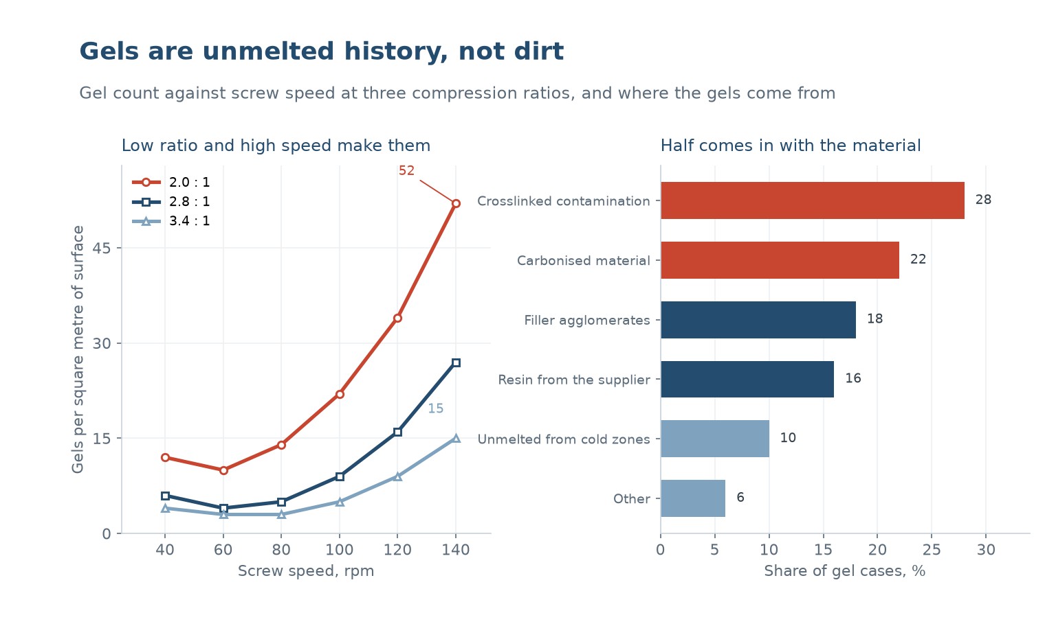
The chart on the left shows gel count against screw speed for three compression ratios. At 40 rpm all three screws produce between 4 and 12 gels per square metre. At 140 rpm the 2.0 to 1 screw produces 52, the 2.8 to 1 produces 27, and the 3.4 to 1 produces 15.
The pattern is the signature of incomplete melting. A low compression ratio does not squeeze the solid bed hard enough against the barrel, so part of it arrives at the metering section still solid. Those particles are then sheared at high stress in a narrow channel, which raises their molecular weight locally instead of melting them.
High screw speed makes it worse for two reasons: the residence time in the compression zone falls, and the shear rate in the metering channel rises. The first reduces the heat the material absorbs, the second creates the conditions for local degradation. Both push in the same direction.
That is why the curves are flat at low speed and steep at high speed. Below about 80 rpm even the 2.0 to 1 screw keeps the count under 15. The problem is not the screw alone, it is the screw run outside the range it was designed for.
Where the material brings them
The chart on the right puts crosslinked contamination at 28 percent and carbonised material at 22. Together, half of all gels are material that has already been damaged before it reaches the die. Crosslinked contamination comes from a previous run of a different material, from a cleaned barrel that was not cleaned well enough, or from resin that was overheated during manufacture.
Carbonised material forms on hot surfaces: the screw flights, the breaker plate, the die land. A film of melt sits on a hot metal surface long enough to oxidise and carbonise, then breaks off in flakes. Those flakes are black, hard and irregular, and they are the easiest gel to identify under a microscope.
Filler agglomerates at 18 percent are a different mechanism. An undispersed filler cluster acts as a stress concentrator and looks like a gel, but it is not a polymer problem. It comes from a compound that was mixed poorly, and no amount of screw speed will disperse it once it has been compounded.
Resin from the supplier at 16 percent is the uncomfortable one. Some grades arrive with a gel count that is within their own specification but too high for a thin film or a clear sheet. Asking for a gel count specification, and testing it on arrival, is the only defence.
Telling them apart
Put the defect under a microscope at 20 to 50 times. A gel has a smooth, rounded, lens shape and a hard centre that resists a needle. An unmelt has the angular outline of a pellet fragment and is soft. A carbon spec is black and brittle. A filler agglomerate is a cluster of fine particles.
Then check where they appear. Gels that are distributed evenly across the width are usually from the material or the screw. Gels concentrated along one edge or in a line suggest a die or a flow problem, where a dead spot is shedding carbonised material at a fixed position.
Finally check the timing. Gels that appear at the start of a run and clear after twenty minutes are start up contamination. Gels that appear after a speed increase are unmelt. Gels that appear gradually over a shift are a dead spot building up.
| Erscheinungsbild | Likely type | First check |
|---|---|---|
| Round, hard, lens shaped | Gel from crosslinking | Resin batch, previous material |
| Angular, soft, pellet shaped | Unmelt | Barrel profile, screw speed |
| Black, brittle, irregular | Carbonised material | Dead spots, die land, breaker plate |
| Cluster of fine particles | Filler agglomerate | Compound dispersion |
| Line along one edge | Die or flow dead spot | Die disassembly and polish |
| Appears at start up only | Kontamination | Purge procedure |
Table 1 — Identifying the defect before changing anything
What actually reduces them
The first fix is to run inside the screw's design range. Reducing the screw speed from 140 to 100 rpm on the 2.0 to 1 screw in the chart cuts the gel count from 52 to 22, which is often enough. It costs output, and it is free.
The second is a proper purge. A purge compound with a high viscosity and an abrasive filler scrubs the screw and the die far better than running the next material through. Purging until the purge itself comes out clean, rather than for a fixed time, is the difference between a clean barrel and a slow bleed of contamination.
The third is a screen pack. A 200 to 400 mesh screen will not stop a gel, because the gel deforms and passes, but it will stop carbonised flakes and unmelted particles. It also raises the back pressure, which improves the melting and reduces the unmelt count. That is why a finer screen often reduces gels indirectly.
The fourth is a different screw. A barrier screw separates the solid from the melt and prevents unmelted material from reaching the die, which is the most effective single fix on a line that is melting limited. It is also the most expensive, and it should come after the first three have been tried.
Specifying against gels
A gel count specification is expressed as a number per unit area, measured on a defined thickness under defined lighting. Without the thickness and the lighting, the number is not comparable, because a gel that is visible in a 50 micrometre film is invisible in a 500 micrometre sheet.
For optical film, counts of 5 per square metre are achievable and 20 is a common reject limit. For a black profile, nobody counts, because nobody can see them. The specification should match the application, and most applications do not need one at all.
| Aktion | Effect on gels | Kosten | Risiko |
|---|---|---|---|
| Reduce screw speed | Minus 50 to 60 % | Lost output | None |
| Purge properly before the run | Minus 40 % at start up | Purge compound | None |
| Finer screen pack | Minus 20 to 30 % | Screen cost, back pressure | Screen breaks if too fine |
| Clean the die and breaker plate | Removes carbon flakes | Ausfallzeit | None |
| Barrier screw | Minus 60 to 70 % | A new screw | Needs a matched barrel |
Table 2 — Options, in the order they should be tried
The order is deliberate. The first four are free or nearly free and together remove most of the problem on a line that is only slightly outside its design range. The screw is for the case where the line has to run at a speed the current screw cannot support.
Why thin products show them first
A gel of 200 micrometres in a 500 micrometre sheet is a small bump. The same gel in a 50 micrometre film is four times the thickness of the product, and it becomes a hole, a tear or a visible defect. That is why film lines have gel specifications and profile lines do not.
The same logic applies to clear products. A gel in a black profile is invisible; in a clear sheet it refracts light and appears as a bright spot, which is far more visible than its size suggests. Clear and thin are the two conditions that turn a minor contamination into a reject.
That is worth remembering when a customer asks for a clear thin product at the output of a line that normally runs thick black profile. The material may be the same and the machine may be the same, but the quality requirement is a different order of magnitude.
What is the difference between a gel and an unmelt?
A gel is polymer with a much higher molecular weight that will not melt at the processing temperature; it is round and hard. An unmelt is a pellet fragment that never got hot enough; it is angular and soft. They look similar and have opposite causes.
Why do I get more gels at higher screw speed?
Less residence time in the compression zone and more shear in the metering channel. The material is not fully melted, and the unmelted particles are sheared hard enough to crosslink locally instead of melting.
Can a screen pack remove gels?
Not the gels themselves, because they deform and pass through the screen. It does remove carbonised flakes and unmelted particles, and the extra back pressure improves melting, so a finer screen usually reduces the count indirectly.
Why do gels appear only at the start of a run?
Start up contamination: material left in the barrel from the previous run, or carbonised film from the last shutdown. A proper purge with an abrasive compound, run until the purge comes out clean, removes it.
Are gels the material supplier's fault?
About a sixth of the time. Crosslinked contamination and carbonised material together are half, and most of that is generated in your own barrel. Ask for a gel count specification and test on arrival to separate the two.
Why are gels a problem in film but not in profile?
Because of relative size. A 200 micrometre gel in a 50 micrometre film is four times the product thickness, so it becomes a hole. In a thick opaque profile the same gel is invisible.
Specks in an extruded product?
Send a photograph of the defect at magnification, the material and the screw speed. We will tell you whether it is a gel, an unmelt or carbon, and what to change first.
Continue reading
- Melt Fracture and Sharkskin: Surface Defects With a Rheological Cause
- Extrusion Purge and Cleaning: Changing Material Without Losing a Shift
- Screen Changers: Filtering the Melt Without Stopping the Line
- Extrusion Screw Design: Compression Ratio, Metering Depth and L/D
- Extrusion Output Rate: What Limits It and What Only Appears To




 DE
 EN
 ES
 FR
 PT
 AR
 RU
 JA
 KO
 IT
 NL
 TR
 PL
 ID
