
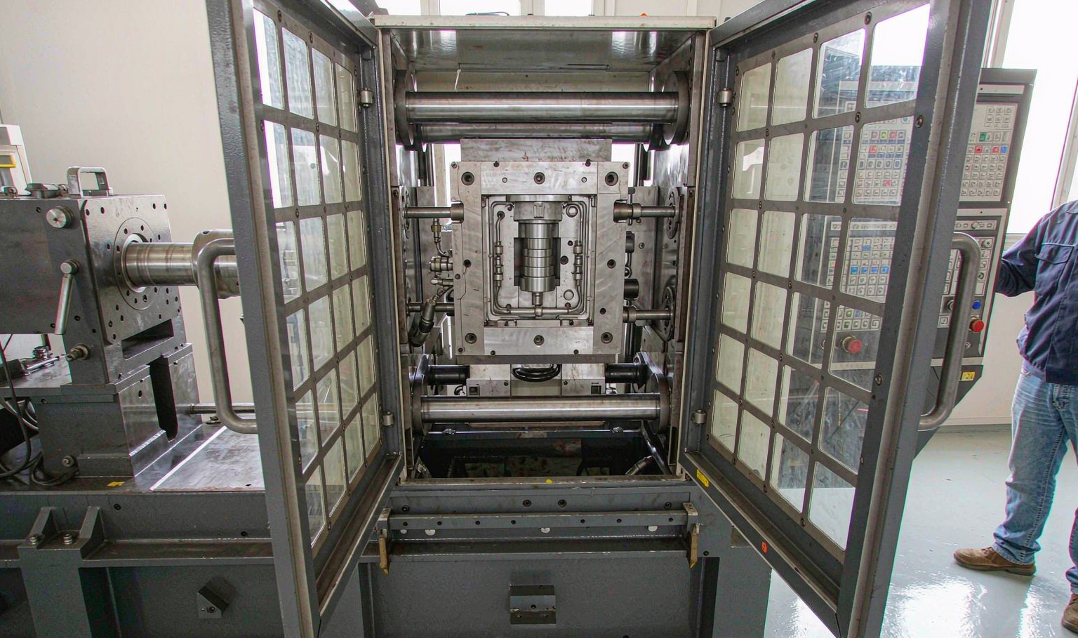
Tonnage is pressure times area, and only one is on the drawing
Clamp force is cavity pressure multiplied by projected area, with a factor for the parts of the mould that are not obvious. The projected area is on the drawing, roughly: the part footprint plus the runner, plus any slide or lifter that sees pressure on a face perpendicular to the clamp. The pressure is not on the drawing, and it is the number that decides whether the calculation is right.
Shops that size tonnage from a table of material constants are using an average, and an average is wrong in both directions. A thin-walled box with a long flow will need nearly twice the pressure of a thick bracket with the same projected area, and a deep part with a large core will need more clamp than its footprint suggests because the material shrinks onto the core and pulls.
The consequence of oversizing is not neutral. A machine running at 30 percent of its rated tonnage has a slow, imprecise clamp, poor tie-bar balance, and a mould that is being compressed by a system with more stored energy than it needs. Undersizing gives flash that no amount of process tuning removes.
Cavity pressure is not the hydraulic gauge
The pressure on the machine gauge is hydraulic. The pressure in the cavity is hydraulic pressure multiplied by the intensification ratio, which is the area of the injection ram divided by the area of the screw. On a typical machine that ratio is between 8 and 12, so a gauge reading of 140 bar corresponds to a melt pressure of 1,120 to 1,680 bar, or 112 to 168 MPa.
| Intensification ratio | Gauge 100 bar gives | Gauge 140 bar gives |
|---|---|---|
| 8 | 80 MPa | 112 MPa |
| 10 | 100 MPa | 140 MPa |
| 12 | 120 MPa | 168 MPa |
Table 1 — Hydraulic pressure against cavity pressure at three intensification ratios
Two machines with the same tonnage and different screws will produce different cavity pressures at the same gauge reading, which is why a process transferred between machines by copying the gauge setting rarely works. Transfer the cavity pressure, or transfer the screw velocity and let each machine find its own hydraulic pressure.
The cavity pressure also is not constant during the cycle. It peaks at the end of fill, drops as the material cools and shrinks, and rises again if packing pressure is applied. The clamp has to resist the peak, and the peak is often 20 to 30 percent above the pressure at the moment of switchover.
Flow ratio sets the pressure before the tool is cut
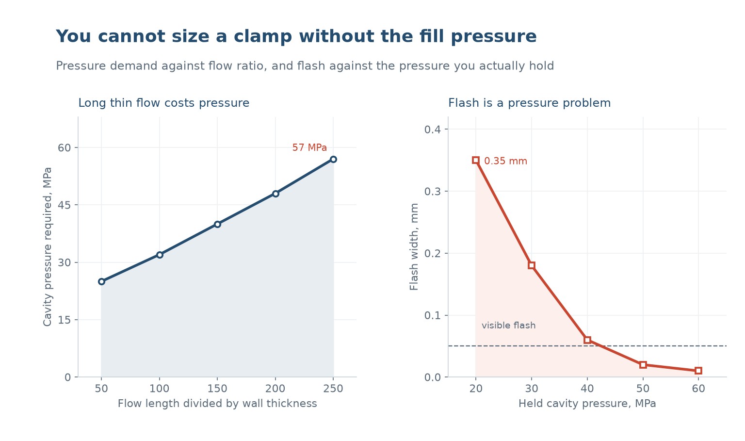
Flow length divided by wall thickness is the best single predictor of the pressure a mould will need. Measured on a family of parts in the same material, a ratio of 50 needs 25 MPa, 100 needs 32, 150 needs 40, 200 needs 48 and 250 needs 57. The relationship is close to linear in the ratio, and it is the reason a thin wall is expensive in tonnage as well as in injection pressure.
That number is available before the tool exists. A part with a 180 mm flow and a 1.2 mm wall has a ratio of 150, which predicts about 40 MPa, which predicts a clamp force of 40 MPa times the projected area times a factor. The calculation takes five minutes and it prevents the most expensive kind of tooling mistake, which is a mould that does not fit the machine it was ordered for.
The prediction is a floor, not a ceiling. Gates, runners, sharp corners and flow imbalances all add pressure, and a part with two cavities of different volumes will need more than the average suggests because the smaller cavity fills first and is then over-packed while the larger one is still filling.
Flash is a pressure problem, not a tonnage problem
Flash appears when the cavity pressure exceeds what the clamp can hold over the projected area, and the parting faces separate by a few microns. Measured flash width against held cavity pressure: 0.35 mm at 20 MPa, 0.18 at 30, 0.06 at 40, 0.02 at 50 and 0.01 at 60. The visible threshold is around 0.05 mm, so the useful transition happens between 30 and 40 MPa.
The shape of that curve is the reason adding tonnage is often the wrong response. Going from 20 to 30 MPa halves the flash. Going from 50 to 60 MPa changes almost nothing, and it costs a heavier machine, more mould wear and a longer clamp cycle. If a mould flashes at 50 MPa, the problem is almost never that 50 is too little.
The real causes, in order of frequency: a damaged or dirty parting line, a vent that is too deep, a mould that is not flat, and a projected area that was underestimated because the runner was left out of the calculation. Adding tonnage to a dirty parting line crushes the dirt into the steel and makes the flash permanent.
There is one case where more tonnage is correct: a deep part with a large core, where the shrinking material grips the core and the ejection force is being mistaken for a clamp problem. That is an ejection and draft issue, and the fix is polish and draft rather than pressure.
Where the safety factor actually belongs
The factor between the calculated force and the machine rating is a decision, not a constant, and it should be written down with a reason.
| Situation | Faktor | Warum |
|---|---|---|
| Simple flat part, one cavity | 1.15 | The calculation is reliable and the failure is cheap |
| Multi-cavity with a runner imbalance | 1.3 | The first cavity to fill is over-packed |
| Deep draw, large core | 1.4 | Shrinkage grip adds an unmodelled force |
| Thin wall, flow ratio above 200 | 1.4 | Pressure prediction has the most error here |
| Engineering resin at high melt temperature | 1.3 | Lower viscosity at temperature means higher pressure reaches the parting line |
Table 2 — Clamp safety factors and the reason for each
The factor is not a substitute for the calculation. A 1.4 applied to a projected area that forgot the runner is still wrong, and it is wrong by more than the factor covers.
What to specify
A clamp specification that can be checked has five lines.
- The projected area, including runner, and whether slides are counted.
- The cavity pressure at the end of fill, from the flow ratio or from a simulation.
- The peak pressure during packing, which is what the clamp actually resists.
- The safety factor, with the reason for the value chosen.
- The machine tonnage, and the percentage of it the process uses, because a process above 85 percent has no room for a cold morning.
Then verify on the machine with a pressure trace rather than with a gauge reading. The trace shows the peak, the switchover and the decay, and it is the only evidence that the number in the calculation is the number in the mould.
How do I calculate clamp force?
Cavity pressure times projected area, including the runner, times a safety factor of 1.15 to 1.4 depending on the part.
What is the intensification ratio?
The area of the injection ram divided by the area of the screw. It converts hydraulic pressure to melt pressure, and it is typically 8 to 12.
What flow ratio needs how much pressure?
Roughly 25 MPa at a ratio of 50, 40 at 150 and 57 at 250. The relationship is close to linear and it can be estimated before the tool is cut.
Why does adding tonnage stop helping?
Because flash width falls steeply between 20 and 40 MPa and almost not at all above 50. Past that point the parting line, not the clamp, is the limit.
Why does a deep part need more clamp than its footprint suggests?
The shrinking material grips the core and adds a force that the projected area does not include. It shows up as flash or as ejection difficulty.
How much of the machine rating should a process use?
Below 85 percent. Above that there is no margin for a cold morning, a material lot change or a worn check ring.
A tool that does not fit the machine?
Send the part drawing with wall thickness and flow length, and the machine tonnage. We will work out the pressure demand before the steel is cut.
Continue reading
- Packing Pressure Profile: The Half Second That Decides the Part
- Injection Speed Profiling: The Fastest Fill Is Not the Cheapest
- Mould Temperature Control: The Variable That Sets Everything Else
- Warpage in Injection Moulding: Differential Shrinkage in Practice
- Custom Injection Moulding: Tooling, Materials and Tolerances




 DE
 EN
 ES
 FR
 PT
 AR
 RU
 JA
 KO
 IT
 NL
 TR
 PL
 ID
