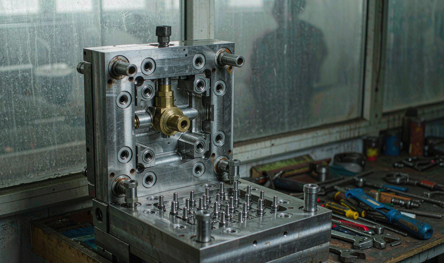
Cooling is a convection problem
Heat leaves a moulded part by conduction through the steel to the channel wall and then by convection into the water. The conduction part is fixed by the steel and the geometry. The convection part is set by the water and it varies by a factor of five depending on how the water is moving.
In laminar flow the water moves in smooth layers, the layer next to the wall is almost stationary, and heat has to cross that layer by conduction. In turbulent flow the water mixes across the channel, the boundary layer is thin, and heat transfer is far more effective.
The transition happens around a Reynolds number of 2,300 to 4,000, which for a 10 mm channel with water at 50 degrees Celsius corresponds to a velocity of roughly 0.8 to 1.2 metres per second. Below that, additional flow does very little; above it, the heat transfer coefficient rises steeply.
This is the single most common cooling problem in a mould shop. The chiller is set to 50 degrees, the manifold shows pressure, and the actual velocity in the channels is 0.4 metres per second because the circuit is long and the hose is small.
What the flow rate actually buys
The chart on the left is the heat transfer coefficient against water velocity for a 10 mm channel with water at 50 degrees Celsius and a 1.5 metre circuit. At 0.2 metres per second the coefficient is 820 watts per square metre kelvin, at 0.8 it is 2,600, at 1.2 it is 3,550 and at 3.5 it is 6,100.
The step change is visible around 1.2 metres per second, which is where the flow becomes fully turbulent. Below that the curve is shallow and steepening; above it the curve is steep and then flattens.
The right hand panel converts that into cooling time. At 0.3 metres per second the cooling time is 26.5 seconds, at 1.2 it is 14.2 and at 2.5 it is 11.9. Going from 0.3 to 1.2 saves 12.3 seconds. Going from 1.2 to 2.5 saves another 2.3.
That is the argument in one line: get above the turbulent threshold, and stop there. Flow beyond about 2.5 metres per second costs pump energy and erodes the channel without buying meaningful cycle time.

Calculating the flow you need
The flow required for a given velocity is the channel cross section times the velocity. For a 10 mm channel that is 78.5 square millimetres, so 1.2 metres per second needs 5.7 litres per minute per circuit.
The number of circuits follows from the mould. A typical medium mould has eight to sixteen circuits, which means 45 to 90 litres per minute at the threshold. A chiller sized on tonnage rather than on flow will often be short of that.
Pressure drop matters too. A long circuit with small fittings may not achieve the flow even if the pump can deliver it, because the pressure is lost in the hose and the quick couplings rather than in the channel. Measure at the mould, not at the chiller.
The practical check is a flow meter on each circuit, or a simple bucket and stopwatch on the return line. If a circuit delivers less than its calculated requirement, the problem is a restriction, a collapsed hose or a manifold that is distributing flow unevenly.
| Channel diameter | Flow for 1.2 m/s | Flow for 2.5 m/s |
|---|---|---|
| 6 mm | 2.0 l/min | 4.2 l/min |
| 8 mm | 3.6 l/min | 7.5 l/min |
| 10 mm | 5.7 l/min | 11.8 l/min |
| 12 mm | 8.1 l/min | 17.0 l/min |
| 14 mm | 11.1 l/min | 23.1 l/min |
Table 1 — Flow per circuit to reach the turbulent threshold.
Measuring at the mould
A chiller panel reading is a system reading. It tells you the total flow and the supply temperature, not what any individual circuit is getting. Circuits are in parallel, so the one with the least resistance takes most of the flow and the one with the most resistance gets almost none.
The usual result is that the circuits cooling the thick section, which are the ones that need flow most, are the longest and get the least. That is why a part with a thick boss is hot at the boss even when the rest of the mould is cold.
Install a flow meter on each circuit, or at least on the circuits that cool thick sections. Balance the manifold so every circuit reaches its calculated flow, and mark the valve positions so they can be restored after maintenance.
Temperature difference between supply and return is a useful secondary check. A circuit with a large difference is removing a lot of heat and may need more flow; a circuit with no difference is not cooling anything and may be blocked or short-circuited.
| Symptom | Likely cause | Check |
|---|---|---|
| Low flow on one circuit | Restriction or closed valve | Flow meter, valve position |
| All circuits low | Pump undersized or filter blocked | Supply pressure, filter |
| Large supply-return difference | Circuit overloaded | Increase flow to that circuit |
| No difference at all | Blocked or short-circuited | Disconnect and flush |
| Flow falls over weeks | Scale or fouling | Water quality, descale |
Table 2 — Diagnosing a cooling circuit from its flow behaviour.
Water quality and fouling
A cooling channel is a heat exchanger, and like any heat exchanger it fouls. Scale from hard water deposits on the wall and insulates it, and the effect is gradual and invisible until the cycle time has crept up by 20 percent over two years.
The remedy is treated water: softened, filtered and with a corrosion inhibitor. A closed loop with a plate heat exchanger to the chiller keeps the mould water clean and is standard on any mould that is expected to run for years.
Biological growth is the other problem in open systems. Algae and bacteria form a film that reduces flow and heat transfer, and it smells. A closed loop with a biocide prevents it.
Flush the circuits on a schedule and inspect the water. A circuit that comes back brown or with flakes needs descaling before it goes back into service, and the mould may need the channels reamed.
Designing for turbulence
Baffles and bubblers exist to get flow into places a drilled channel cannot reach, and they work only if the flow is high enough. A bubbler in a 12 mm core with 2 litres per minute is a laminar trickle and cools almost nothing.
Conformal cooling changes the geometry so the channel follows the part surface, which shortens the heat path and allows a smaller channel closer to the surface. It does not remove the need for turbulent flow, and a conformal channel running laminar is no better than a drilled one.
Channel diameter is a design compromise. A larger channel gives more flow at the same velocity but removes more steel and weakens the mould. Ten millimetres is a common compromise for medium moulds; smaller channels need proportionally higher pressure to reach the same velocity.
The design review question is simple: for each circuit, what velocity does the pump deliver at the working pressure, and is it above 1.2 metres per second. If the answer is no, the cooling layout is theoretical.
What water velocity should a mould cooling channel run at?
At least 1.2 metres per second to be fully turbulent. Below about 0.8 the flow is laminar and heat transfer collapses regardless of temperature.
How much flow does a 10 mm cooling channel need?
About 5.7 litres per minute for 1.2 metres per second, and 11.8 for 2.5. Multiply by the number of circuits in parallel to size the supply.
Does more flow always reduce cooling time?
Up to about 2.5 metres per second it helps. Beyond that the gain is small and the pump energy and channel erosion keep rising.
Why is my part hot at the thick boss?
The circuits cooling the thick section are usually the longest and get the least flow in a parallel manifold. Measure flow per circuit and balance the manifold.
Why does cooling performance drop over years?
Scale and fouling insulate the channel wall. Treated water in a closed loop with a plate heat exchanger prevents most of it.
Should I read flow at the chiller or at the mould?
At the mould. The chiller reading is a system total, and parallel circuits distribute flow unevenly, so individual circuits can be starved while the total looks correct.
Cycle time limited by cooling?
Send the mould layout and the chiller specification. We will check whether the channels are actually reaching turbulent flow.






 EN
 ES
 FR
 DE
 PT
 AR
 RU
 JA
 KO
 IT
 NL
 TR
 PL
 ID