
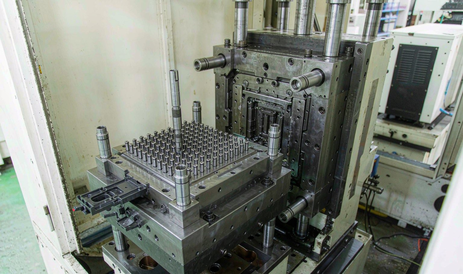
Ejection is a force divided by an area
A part shrinks onto the core as it cools. The shrink is what holds it there, and the hold is proportional to the interference, the contact area and the coefficient of friction between the plastic and the steel. Ejection has to overcome that hold, and the number is often larger than the injection force people expect.
The mark the ejector leaves is that force divided by the area it pushes on. This is the whole of ejection design in one sentence: the same force over twice the area is half the pressure, and half the pressure is half the mark. Everything else, the draft, the pin count, the pin diameter, the polish, is a way of changing one of those two numbers.
Which is why a part that ejects badly is rarely fixed by a bigger ejector plate. It is fixed by reducing the force, and the cheapest way to reduce the force is not more pins. It is more draft.
Draft is cheaper than force
Draft angle reduces the interference directly. At half a degree the ejection force index is 100. At one degree it is 67, at one and a half it is 51, at two it is 44, and at three it is 38.
The first half degree is worth more than the next two. Going from 0.5 to 1.0 degrees removes a third of the force; going from 1.0 to 2.0 removes another third of what is left; going from 2.0 to 3.0 removes almost nothing. That is why the standard recommendation is one to two degrees and not three: past two degrees you are spending part geometry for a gain that is no longer there.
The catch is that draft has to come out of the part, and on a deep rib or a tall boss the customer notices. A tenth of a millimetre of draft per 5 mm of depth is invisible; a degree on a 100 mm wall is 1.7 mm and it is not. The honest answer is that a deep feature with no draft will scuff, and the fix is a slide or a redesign, not a bigger pin.

More pins, less mark
If the force cannot come down, spread it. At a constant total force, two ejector pins leave a mark 42 microns deep. Four pins give 29 microns, six give 19, eight give 12, and twelve give 6.
The curve flattens, and it flattens for a reason: the mark depth is not purely a pressure effect. Some of it is elastic recovery, and below about 10 microns the plastic springs back far enough that the mark is no longer measurable with a profilometer. Pushing past twelve pins to twenty buys almost nothing except tooling cost.
The real limit on pin count is not the mark, it is the space. Pins cannot go where the part has a thin wall, a boss on the other side, a cooling channel underneath or a cosmetic surface. On a deep box the pins can only sit on the base, and the base is often the one place the customer will look.
The other limit is balance. Six pins on one side of the part and two on the other is worse than eight pins evenly spread, because an unbalanced ejection tilts the part on the core and the tilt marks the side wall far more than the pins mark the base.
Pin, sleeve, stripper, air
A pin pushes on a small area. It is cheap, it is easy to place, and it leaves a localised mark. It suits a flat base, a thick section and a non-cosmetic surface.
A sleeve surrounds a core pin and pushes on an annulus, so it is the only ejector that can push on a cylindrical boss without leaving a ring in the middle of it. It is the standard for a deep tube, a cap or a boss with a tight bore.
A stripper plate pushes on the whole perimeter of the part with a plate that travels with the mould opening. It leaves no local mark at all, and it is the only option for a thin walled cup where any pin would go through. It costs a plate, a guide system and a lot of space.
Air ejection blows the part off with a burst of compressed air through a porous insert or a valve. It leaves nothing, it works on a part with no ejector flat at all, and it needs a compressor, a valve and a clean air supply. On a thin walled part with a large flat face it is often the cheapest answer in total.
| Type | Contact | Mark | Best for |
|---|---|---|---|
| Pin | Point | Local, 6-42 microns | Flat base, thick section |
| Sleeve | Annulus | Ring at the boss | Deep tube, cap, boss |
| Stripper plate | Perimeter | None | Thin walled cup, cosmetic |
| Air | Whole face | None | Large flat part, no flat to push |
| Blade | Line | Line | Rib, thin flat part |
Table 1 — Ejector types and the mark each one leaves
Where a mark is allowed
A mark on a hidden face is not a defect. A mark on the A surface is a reject. That sounds obvious and it is routinely ignored, because the ejector layout is drawn by the toolmaker at the end of the design, usually after the cooling circuit has taken all the space on the core side.
Texture hides a mark better than anything else. A 0.3 mm deep grain will swallow a 20 micron step completely, while a polished face shows 5 microns as a shadow. A part that will be textured can take pins in places a glossy part cannot.
A mark near the gate is usually acceptable, because the gate is trimmed and the area around it is already a witness. A mark in the middle of a visible face is not, and on a part like that the answer is a stripper or air, or a gate and ejector layout that puts the push where nobody looks.
There is also a tolerance on the mark itself, and it should be written down. 10 microns is invisible on a textured part and detectable on a polished one; 40 microns is visible on anything. A drawing that says nothing about ejector marks gets whatever the toolmaker's default is.
Ejection is where warpage is decided
A part that is ejected too hot bends, and it bends in the direction the ejectors pushed. The plastic is still soft, the ejector force is applied unevenly, and the part takes a permanent set that no amount of packing would have caused. Ejection at the wrong temperature is a warpage cause that looks like a cooling problem.
The fix is usually a longer cooling time, which costs cycle, or a better balanced ejector layout, which does not. Before adding cooling time, check whether the part is being pushed off straight. A dial indicator on the ejector plate and a look at the part as it comes off will tell you more than another thermocouple.
Ejection also interacts with draft in a way that shows up late. A part with marginal draft ejects with a scuff on the first shots, the scuff polishes the core, the polished core grips more, and the scuff gets worse. It is a self-reinforcing failure, and it is why a marginal draft is never really marginal.
The order the decisions should be made
Draft first, because it is a part geometry decision and it is cheapest before the tool is cut. Then the ejector type, because a stripper needs space in the tool design that cannot be added later. Then the layout, balanced around the centre of the projected area. Then the count, from the mark tolerance. Then the return springs and the stroke.
The stroke has to clear the part, not just reach it. A part that is 40 mm deep needs the ejector to travel more than 40 mm or it will be dragged off the core by the robot instead of pushed. That is a machine specification, and it is checked after the tool is designed far too often.
| Decision | Driven by | Cost if late |
|---|---|---|
| Draft | Part geometry, depth | A new tool |
| Ejector type | Cosmetic face, wall | A redesign |
| Layout | Projected area, cooling | A new core insert |
| Pin count | Mark tolerance | Rework, or accept |
| Stroke | Part depth, machine | A different machine |
Table 2 — Ejection decisions in the order they should be made
How much draft does a part need?
One to two degrees on most surfaces, and half a degree more on a textured or deep feature. Going from 0.5 to 1.0 degrees cuts the ejection force by a third, which is more than any pin layout can do.
Why does my part have ejector marks?
Because the force per unit area is too high. Either reduce the force with more draft or a lower demoulding temperature, or spread it over more or larger pins. A mark of 10 microns is invisible on a textured part and 40 is visible on anything.
When should I use a stripper plate?
On a thin walled cup or any part where a pin would go through the wall, and on a part with a fully cosmetic face. It leaves no local mark, but it needs a plate, guides and space in the tool.
Can ejector marks be polished out?
Only if the mark is a raised witness, not a depression. A pin leaves a depression and polishing it removes material from the cosmetic face, which changes the part. The fix is upstream.
Does ejection cause warpage?
It can. A part ejected while still soft, pushed unevenly, takes a permanent set in the direction of the push. That looks like a cooling problem and is fixed by a balanced layout or a longer cool.
How much ejector stroke is needed?
More than the part depth, so the part clears the core before the robot takes it. A 40 mm deep part needs more than 40 mm of travel, and the machine has to be specified for it.
A part that sticks, scuffs or comes out with marks?
Send the part drawing and a photo of the mark. We will tell you whether it is draft, layout or demoulding temperature, and what the ejector should look like.
Continue reading
- Warpage in Injection Molding: Differential Shrinkage and the Fix
- Gate Design in Injection Molding: Where the Plastic Enters
- Cooling Time Optimization: The Part Is Cold When It Leaves
- Injection Cycle Time Reduction: Where the Seconds Actually Are
- Custom Injection Molding: Tooling, Tolerances and Volume




 EN
 ES
 FR
 DE
 PT
 AR
 RU
 JA
 KO
 IT
 NL
 TR
 PL
 ID
