
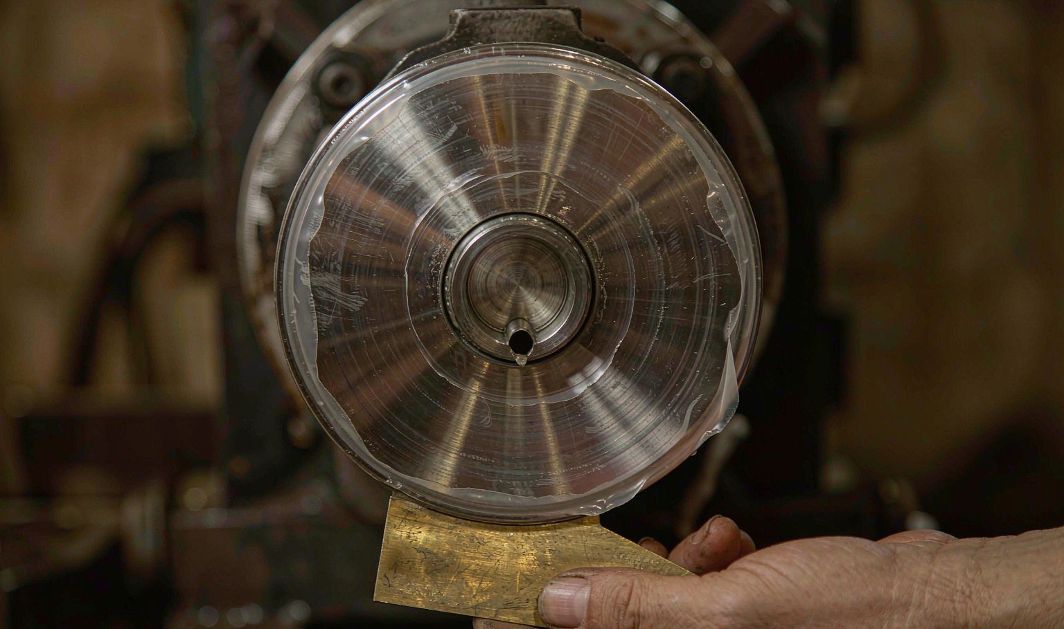
- 1. What a profile die actually has to do
- 2. The anatomy of a profile die
- 3. Land length: the number that decides surface quality
- 4. Die swell: why the die is not the part shape
- 5. Balancing flow: restrictors, chokes and the flow-splitting problem
- 6. Hollow profiles: spiders, bridges and the weld line problem
- 7. The die is only half the tool: calibration and sizing
- 8. Die materials and the wear question
- 9. Design rules that reduce die cost
- 10. The trial cut cycle, and how many you should budget
- 11. Frequently asked questions
- 12. Send the section drawing — we will tell you what the die can and cannot do
What a profile die actually has to do
A profile die is not a shaped hole. It is a flow-balancing device. The shape of the orifice is almost the last thing you design, and on most dies the orifice is not even the same shape as the finished profile.
The die has to deliver melt to every point of the land at the same velocity, at the same temperature, and at the same pressure. Where it fails, the profile comes out with one wall running fast and another running slow, and no amount of downstream calibration will fix it — calibration can hold a shape, but it cannot make an unbalanced flow balanced.
Three things make this difficult:
- The flow path from the extruder is round and the profile is not. Melt enters as an annulus or a rod and has to be redistributed into a shape that may be a hollow box, a T, a J-channel, or a complex multi-wall window profile.
- Flow resistance scales with the cube of the gap. In a wide, thin section, a 10 % variation in land depth produces roughly a 30 % variation in flow. Small machining errors become large flow errors.
- The polymer is viscoelastic. It swells when it leaves the die, and it swells differently depending on shear rate, temperature and the shape of the land. The die has to be cut smaller than the profile, in a pattern that is not a uniform scale-down.
The single most useful mental model: think of the die as a set of parallel pipes feeding one common outlet. Every "pipe" (each wall of the profile) has to have the same resistance, so that the same pressure pushes the same amount of melt through each. Die design is the business of adjusting those resistances — with land length, with channel depth, and with flow restrictors.
The anatomy of a profile die
Almost every profile die has the same five zones, in this order. Understanding what each one does makes the design decisions obvious.
| Zone | Function | Typical length | What goes wrong |
|---|---|---|---|
| Inlet / adapter | Connects the extruder to the die, often with a breaker plate and screen pack | 50 – 150 mm | Dead spots where material hangs up and degrades |
| Transition / distributor | Reshapes the round melt stream into a rough approximation of the profile | 80 – 250 mm | Uneven velocity entering the land — the most common root cause of imbalance |
| Flow channel | Balances resistance across the section, often with a choke or restrictor bar | 50 – 200 mm | Local hot or slow zones, weld lines, stagnation |
| Land | Final shaping, and generating enough back pressure for the melt to be uniform | 10 – 60 mm | Too short: rough surface. Too long: high head pressure, melt fracture |
| Die lip / exit | Defines the final dimensions, including die swell allowance | 2 – 10 mm | Nicks and burrs that print a line down the whole profile |
Lengths are for a profile with a circumscribed diameter of 50 – 150 mm. Small profiles scale down; large hollow profiles with spider dies need much longer distributors.
Land length: the number that decides surface quality
Land length is the straight, parallel section at the die exit. It does two jobs at once, and they pull in opposite directions.
- Longer land = smoother surface. The melt has more time to relax its elastic deformation before it leaves, so die swell is reduced and surface roughness (sharkskin, melt fracture) is suppressed.
- Longer land = higher head pressure. Pressure at the die rises roughly linearly with land length, which increases melt temperature, increases motor load, and can push the screw into a less stable operating point.
| Section thickness | Minimum land | Typical land | Long land (for surface) |
|---|---|---|---|
| < 1.0 mm | 5 × thickness | 8 – 12 × thickness | 15 × thickness |
| 1.0 – 2.0 mm | 6 – 8 mm | 10 – 20 mm | 25 mm |
| 2.0 – 4.0 mm | 10 mm | 20 – 35 mm | 45 mm |
| 4.0 – 8.0 mm | 15 mm | 30 – 50 mm | 70 mm |
| > 8.0 mm | 20 mm | 40 – 70 mm | 90 mm |
Rule of thumb: land should be at least 5× the section thickness, and preferably 10×. Below 5× the surface will be matt or rough and die swell will be high and variable.
There is a second rule that matters more on multi-wall profiles: the land length should be proportional to the local wall thickness, not constant. A profile with a 3 mm outer wall and a 1.2 mm internal rib needs a longer land on the thick wall and a shorter one on the rib, so that both see the same resistance. Cutting a constant land around a variable-thickness profile is one of the most common die design errors, and it shows up as a thick wall that runs fast and a thin rib that starves.
Die swell: why the die is not the part shape
When melt leaves the die it relaxes, and the extrudate becomes thicker than the orifice. The ratio of extrudate thickness to orifice thickness is the die swell, and it is typically 1.05 – 1.5 for profile extrusion, depending on material and shear rate.
| Material | Typical die swell | Notes |
|---|---|---|
| Rigid PVC (dry blend) | 1.05 – 1.20 | Low and predictable — easy to compensate |
| Flexible PVC | 1.10 – 1.30 | Higher plasticiser content, higher swell |
| HDPE | 1.25 – 1.50 | High and strongly shear-dependent |
| PP | 1.20 – 1.45 | High; also high and anisotropic shrinkage |
| ABS | 1.10 – 1.25 | Moderate |
| PC | 1.05 – 1.20 | Low swell but high melt viscosity |
| PMMA | 1.05 – 1.15 | Low |
| PA (nylon) | 1.15 – 1.35 | Very shear-sensitive; swells more at low output |
| POM | 1.10 – 1.25 | — |
| TPE / TPV | 1.15 – 1.40 | High, and strongly dependent on hardness |
Values at typical profile extrusion shear rates. Swell falls as shear rate rises, so a die cut for one output rate will be wrong at a very different rate.
Three practical consequences:
- Swell is not uniform. A thin wall swells proportionally more than a thick one, because it experienced a higher shear rate. So the die cannot be a simple scaled-down version of the profile — the thin sections need proportionally more allowance than the thick ones.
- Swell is not isotropic. It happens mostly in the direction of relaxation, which on a complex profile means corners bulge and flats stay flatter. This is why a die cut to a mathematically correct offset shape still produces a rounded, distorted profile.
- The die is cut by trial. First cut, run it, measure the extrudate without calibration, then adjust. Trying to hit final dimensions on the first cut is a waste of a die blank — you will cut it three times anyway, so cut it undersize and work up.
The practical sequence: cut the die 3 – 5 % undersize on the thick walls and 8 – 12 % undersize on the thin walls, run it into free air with no calibrator, measure the swell on every wall, then adjust each wall individually. Only when the free extrudate is dimensionally even do you fit the calibrator. Balancing the die downstream of a calibrator hides the problem instead of fixing it.
Balancing flow: restrictors, chokes and the flow-splitting problem
On any profile that is not a simple symmetric shape, the melt will prefer the short, thick path. The die has to be given artificial resistance in the easy paths so that flow is equalised.
| Technique | How it works | Where it is used | Drawback |
|---|---|---|---|
| Land length variation | Longer land = more resistance | Simple profiles, small differences | Fixed once cut — no adjustment in production |
| Choke / restrictor bar | A removable insert that narrows the channel | Large profiles, wide flats | Creates a dead spot if not streamlined |
| Adjustable restrictor screws | Set screws that deflect a flexible lip | Production dies, wide sheet-like sections | Only works where the die has a flexible member |
| Flow splitting (spider / bridge) | Melt is divided and recombined around a core | Hollow profiles | Leaves weld lines |
| Temperature profiling | Hotter die zone = lower viscosity = more flow | Fine tuning on any die | Limited range; can cause degradation |
| Die land inserts | Replaceable lips for wear or size change | High-volume dies, abrasive compounds | Extra cost, extra leak path |
Most production dies use a combination: land length for the coarse balance, a choke for the wide sections, and die temperature zoning for the final trim.
The balancing act is easier if the die is designed around equal residence time rather than equal velocity. Material that spends much longer in one part of the die than another will be at a different temperature when it reaches the land, and temperature differences of 5 – 10 °C are enough to visibly unbalance a profile. Long, slow paths need to be shortened or heated, not just restricted.
Hollow profiles: spiders, bridges and the weld line problem
A hollow profile needs a core in the die to form the inside, and the melt has to get around that core. There are two ways, and both leave a mark.
Spider die
The core is supported by several legs (spider legs) that cross the flow channel. Melt splits around each leg and recombines downstream. The recombination line is a weld line, and it is a permanent feature of the profile — weaker, often visible, and sometimes a crack initiation point.
Spider dies are simple, cheap and work well for round tube and simple hollow sections in materials that weld well (PVC, PE, PP). They are poor for engineering resins and for any profile where the weld line falls on a visible face.
Bridge die
The core is supported by a bridge that sits in the die body rather than crossing the flow directly. The melt flows over the bridge, joins in a chamber behind it, and then passes through the die orifice with the core in the centre. The weld line is pushed further upstream and has more length and pressure to heal in, so the weld is stronger than in a spider die.
Bridge dies are the standard for hollow profiles in engineering resins, and for any profile where the weld line must be as strong as the parent material.
| Feature | Spider die | Bridge die |
|---|---|---|
| Weld line strength | 50 – 80 % of parent | 80 – 95 % of parent |
| Die cost | Base | +30 – 60 % |
| Minimum hollow size | Small hollows possible | Larger hollows only |
| Best for | PVC, PE, PP tube and simple hollows | Engineering resins, pressure parts, visible faces |
| Pressure drop | Lower | Higher |
| Cleanout | Easy | Harder — more hidden volume |
On any hollow profile, the weld line position should be agreed with the customer at design stage. If the profile is a visible window frame, the weld must be placed where it cannot be seen, or the die must be a bridge design.
The die is only half the tool: calibration and sizing
After the die, the profile passes into a calibrator — a sleeve, usually of brass, aluminium or steel, that holds the profile to size while it cools. The calibrator does not shape the profile; it holds a shape the die has already produced. This distinction matters because buyers often blame the calibrator for a problem that is in the die.
| Symptom | Die problem | Calibrator problem |
|---|---|---|
| One wall thick, opposite wall thin | Yes — unbalanced flow | No |
| Overall size drifting over a run | Possible — die temperature drift | Possible — vacuum loss, wear |
| Corners rounded, flats pulled in | Possible — insufficient corner flow | Yes — vacuum too high or holes misplaced |
| Surface marks in a repeating pattern | No | Yes — blocked vacuum slots or dirt |
| Profile twisted along its length | Possible — uneven die temperature | Yes — uneven cooling around the section |
| Dimensions correct but surface rough | Yes — land too short | No |
A useful diagnostic: run the profile into free air, without the calibrator. If the imbalance is still there, it is the die. If the free extrudate is even and the calibrated profile is not, it is the calibrator or the cooling.
Die materials and the wear question
Profile dies are almost always steel, but which steel depends on the compound and the volume.
| Die material | Hardness | Relative cost | Best for |
|---|---|---|---|
| Carbon steel (1.2311 / P20) | 30 – 34 HRC | 1.0× | Short runs, unfilled PVC and polyolefins |
| Through-hardened tool steel | 48 – 54 HRC | 1.4 – 1.8× | General production, moderate filler |
| Nitrided steel | Surface 60 – 65 HRC | 1.5× | Abrasive fillers — best cost/benefit for CaCO₃ and talc |
| Stainless (420 / 1.2083) | 48 – 52 HRC | 1.8 – 2.2× | Corrosive compounds, medical, food contact |
| Tungsten carbide inserts | — | 4 – 8× on the land | Highly filled, glass-fibre, very high volume |
Wear shows first at the land, where shear rate is highest. A nitrided land is usually the cheapest way to triple die life on a filled compound.
Two wear notes that come up in practice:
- Calcium carbonate is more abrasive than talc at the same loading, and glass fibre is far worse than either. A die that lasts five years on unfilled PVC may last eight months on 30 % glass-filled PA.
- Wear changes dimensions slowly and silently. A die that has worn 0.05 mm on the land produces a profile that is consistently 0.05 mm over and cannot be brought back by adjusting the line. Checking land dimensions at every major service is the only way to catch it before the customer does.
Design rules that reduce die cost
Most of the die cost is machining time, and most machining time is in the flow channel. A profile designed with the die in mind is cheaper to tool and easier to run.
| Design choice | Effect on die cost | Effect on running |
|---|---|---|
| Uniform wall thickness | Large reduction — one land depth instead of five | Much easier to balance |
| Generous internal radii (≥ 0.5 × wall) | Moderate reduction | Better flow at corners, fewer sink marks |
| Symmetric section where possible | Moderate reduction | Reduces twist |
| Avoid very thin ribs (< 0.8 mm) | Reduction — thin ribs need separate inserts | Ribs starve; hard to calibrate |
| Keep the circumscribed circle small | Large reduction — die size follows | Better temperature uniformity |
| Avoid undercuts and re-entrant angles | Large reduction | Calibrator becomes possible in one piece |
| Hollow sections with round or oval cores | Reduction — simpler core support | Stronger weld line |
The first row alone typically accounts for 20 – 40 % of die cost on a complex profile. A section with five different wall thicknesses needs five separately balanced lands and usually three or four trial cuts.
The trial cut cycle, and how many you should budget
Nobody cuts a profile die right the first time. The realistic expectation is 2 – 4 trial cuts, and the quote should reflect that.
- Cut 1 — undersize, run in free air. Measure swell on every wall. Expect the thick walls to be close and the thin walls to be 5 – 15 % off.
- Adjust — change land length and local channel depth. Weld or insert rather than remove material where possible, so the die can be cut back again if needed.
- Cut 2 — run with the calibrator. Now measure the finished profile. Correct residual imbalance and die swell together.
- Cut 3 — final trim. Small corrections to individual walls, usually 0.02 – 0.10 mm.
- Sign-off — run 30 minutes at production rate and measure at start, middle and end. A die that is right at minute two and wrong at minute thirty has a thermal problem, not a dimension problem.
What buyers get wrong: assuming the die is a one-off purchase that arrives correct. A profile die is a development process with a tool attached. Budgeting three trial cuts and two weeks of sampling is normal; expecting first-off approval is not, and it is the single most common cause of a project running late.
Frequently asked questions
How long does it take to make a profile extrusion die?
For a simple solid profile, 2 – 4 weeks including one trial cut. For a complex multi-wall or hollow profile, 6 – 10 weeks, because the flow channel is more difficult to machine and two or three trial cuts are normal.
Why is my extruded profile bigger than the die?
Die swell. The melt relaxes as it leaves the die and expands, typically by 5 – 50 % depending on material and shear rate. The die is cut smaller than the finished profile to compensate, with more allowance on thin walls than thick ones because thin walls see higher shear.
What is land length and why does it matter?
The straight parallel section at the die exit. A longer land gives the melt time to relax, producing a smoother surface and lower die swell, but it raises head pressure. A useful minimum is 5× the wall thickness; 10× is better for surface quality.
Can I change the profile size without a new die?
Within about ±3 % by adjusting haul-off speed (drawdown) and die temperature, and more if the die has replaceable land inserts. Beyond that the flow balance changes and a new die or a re-cut land is needed.
Why does my hollow profile crack along a line?
That is the weld line from the spider or bridge. In a spider die the weld is typically 50 – 80 % of parent strength and can crack under impact or internal pressure. A bridge die raises this to 80 – 95 %. If the part is pressure-rated, the weld position and strength have to be designed in, not discovered in testing.
How much does a profile extrusion die cost?
Roughly $1,500 – 6,000 for a simple solid profile under 100 mm, $6,000 – 20,000 for a multi-wall or hollow profile, and $20,000 – 60,000+ for a large complex window or door profile with calibration. Calibrators are usually 30 – 60 % of the die cost on top.
Why does my profile have a rough, matte surface?
Usually the land is too short, the melt is too cold, or the output is too high for the die. Sharkskin (fine transverse cracks) is a specific form of melt fracture that appears when the shear rate at the die wall exceeds a critical value — the fix is higher melt temperature, a longer land, or a lower output.
Should the die be heated separately from the extruder?
Yes, on almost all profile dies. Independent die zones let you trim the flow balance without changing the melt condition in the barrel, and they let you compensate for the heat the die loses to the calibrator and the surroundings. A die with no independent heating is very difficult to balance.
What is drawdown and how much should I use?
Drawdown is the ratio of die orifice size to finished profile size, achieved by pulling the profile faster than it exits. Typical values are 1.05 – 1.25 for profiles. More drawdown reduces die swell effects but increases orientation and shrinkage, and it makes dimensional control harder.
Can one die make two different sizes?
Only with replaceable land inserts, and then only within a limited range. Changing the land changes the flow balance, so a die with inserts is really two dies that share a body — useful for a product family where the wall thickness is the same and only the width changes.
Send the section drawing — we will tell you what the die can and cannot do
We review the profile for wall uniformity, hollows, weld line position and calibration feasibility before quoting, and we tell you which design changes cut the die cost. DWG, DXF or a dimensioned PDF is enough.




 EN
 ES
 FR
 DE
 PT
 AR
 RU
 JA
 KO
 IT
 NL
 TR
 PL
 ID
